
Solar-Powered TP4056 Battery Charger with LED Indicator and Rocker Switch
View and Edit Project In Cirkit Designer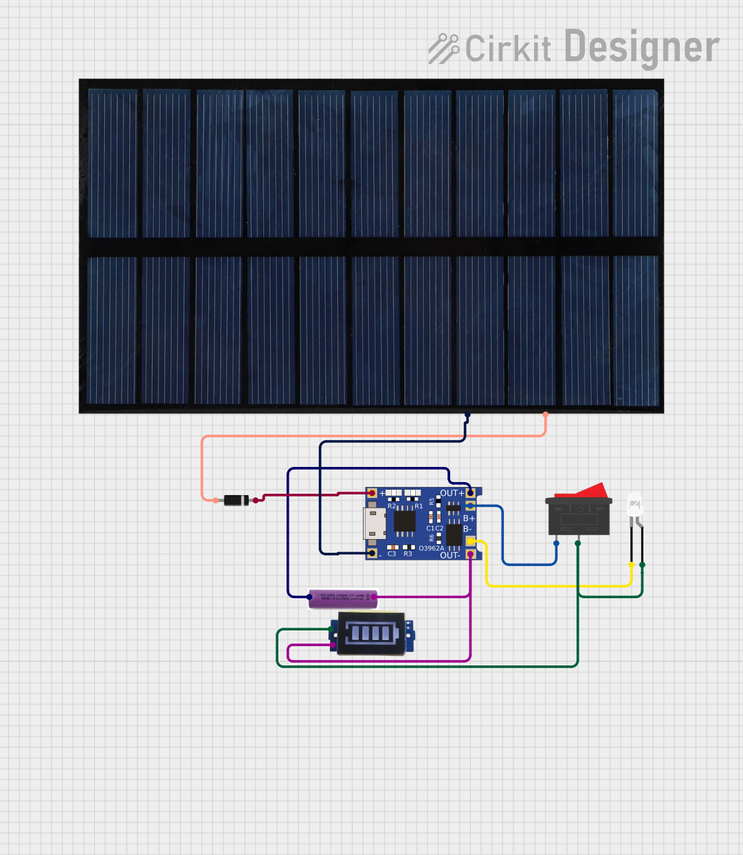
Circuit Documentation
Summary of the Circuit
This circuit is designed to charge a 3.7V battery using a TP4056 charger module, with power supplied by a solar cell. It includes a battery indicator to monitor the charge status, a rocker switch to control the power flow, and a white LED as an indicator or for illumination. A diode is used to prevent reverse current from the battery to the solar cell. The circuit does not include any microcontroller or embedded code.
Component List
TP4056
- Description: A lithium battery charger and protection module.
- Pins: OUT-, B-, B+, OUT+, IN-, IN+
3.7v Battery
- Description: A rechargeable lithium battery.
- Pins: +, -
Rocker Switch
- Description: A switch to control the connection of the circuit.
- Pins: 1, 2
LED: Two Pin (white)
- Description: A white light-emitting diode.
- Pins: cathode, anode
Solar Cell
- Description: A photovoltaic cell that converts sunlight into electrical energy.
- Pins: +, -
Diode
- Description: A semiconductor device that allows current to flow in one direction only.
- Pins: cathode, anode
Battery Indicator
- Description: A module that indicates the charge level of the battery.
- Pins: Positive, Negative
Wiring Details
TP4056
- OUT- connected to the negative terminal of the 3.7v battery and the Negative pin of the Battery Indicator.
- B- connected to the cathode of the LED.
- B+ connected to pin 1 of the Rocker Switch.
- OUT+ connected to the positive terminal of the 3.7v battery.
- IN- connected to the negative terminal of the Solar Cell.
- IN+ connected to the cathode of the Diode.
3.7v Battery
- + connected to the OUT+ of the TP4056.
- - connected to the OUT- of the TP4056, the Negative pin of the Battery Indicator.
Rocker Switch
- 1 connected to the B+ of the TP4056.
- 2 connected to the Positive pin of the Battery Indicator and the anode of the LED.
LED: Two Pin (white)
- cathode connected to the B- of the TP4056.
- anode connected to pin 2 of the Rocker Switch and the Positive pin of the Battery Indicator.
Solar Cell
- + connected to the anode of the Diode.
- - connected to the IN- of the TP4056.
Diode
- cathode connected to the IN+ of the TP4056.
- anode connected to the positive terminal of the Solar Cell.
Battery Indicator
- Positive connected to pin 2 of the Rocker Switch and the anode of the LED.
- Negative connected to the negative terminal of the 3.7v battery and the OUT- of the TP4056.
Documented Code
There is no embedded code provided for this circuit as it does not include any programmable components or microcontrollers.