
Circuit Documentation
Summary of the Circuit
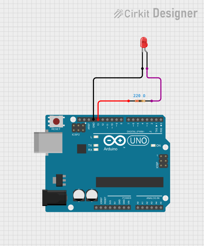
This circuit is designed to control a red two-pin LED using an Arduino UNO microcontroller. The LED is connected to digital pin D13 of the Arduino and blinks on and off every second. A current-limiting resistor is placed in series with the LED to prevent damage to the LED by limiting the current flowing through it. The circuit demonstrates the basic digital output functionality of the Arduino by toggling the voltage on pin D13 between high and low states.
Component List
Arduino UNO
- Description: A microcontroller board based on the ATmega328P.
- Purpose: Acts as the control unit for the LED blinker circuit.
- Pins: UNUSED, IOREF, Reset, 3.3V, 5V, GND, Vin, A0-A5, SCL, SDA, AREF, D0-D13.
LED: Two Pin (red)
- Description: A basic red light-emitting diode.
- Purpose: Emits light when powered.
- Pins: cathode, anode.
Resistor
- Description: A passive two-terminal electrical component that implements electrical resistance as a circuit element.
- Purpose: Limits the current flowing through the LED to prevent damage.
- Properties: Resistance value of 220 Ohms.
Wiring Details
Arduino UNO
- GND is connected to the cathode of the LED.
- D13 is connected to pin1 of the Resistor.
LED: Two Pin (red)
- Cathode is connected to GND on the Arduino UNO.
- Anode is connected to pin2 of the Resistor.
Resistor
- Pin1 is connected to D13 on the Arduino UNO.
- Pin2 is connected to the anode of the LED.
Documented Code
sketch.ino
/*
  LED Blinker Circuit
  This sketch controls an LED connected to pin D13 of the Arduino UNO.
  The LED blinks on and off every second. This circuit demonstrates basic
  digital output functionality of the Arduino by using a digital pin to
  provide a voltage to an LED through a current-limiting resistor.
*/

// Define the LED pin
const int ledPin = 13;

// the setup function runs once when you press reset or power the board
void setup() {
  // initialize digital pin ledPin as an output.
  pinMode(ledPin, OUTPUT);
}

// the loop function runs over and over again forever
void loop() {
  digitalWrite(ledPin, HIGH);   // turn the LED on (HIGH is the voltage level)
  delay(1000);                  // wait for a second
  digitalWrite(ledPin, LOW);    // turn the LED off by making the voltage LOW
  delay(1000);                  // wait for a second
}
This code is responsible for blinking the LED connected to pin D13 of the Arduino UNO. The setup() function initializes the pin as an output. The loop() function then repeatedly turns the LED on and off, with a one-second delay between each state change.