Cirkit Designer
Your all-in-one circuit design IDE
Home /
Project Documentation
Arduino-Based Air Quality Monitoring System with Gas Sensors and LCD Display
Circuit Documentation
Summary
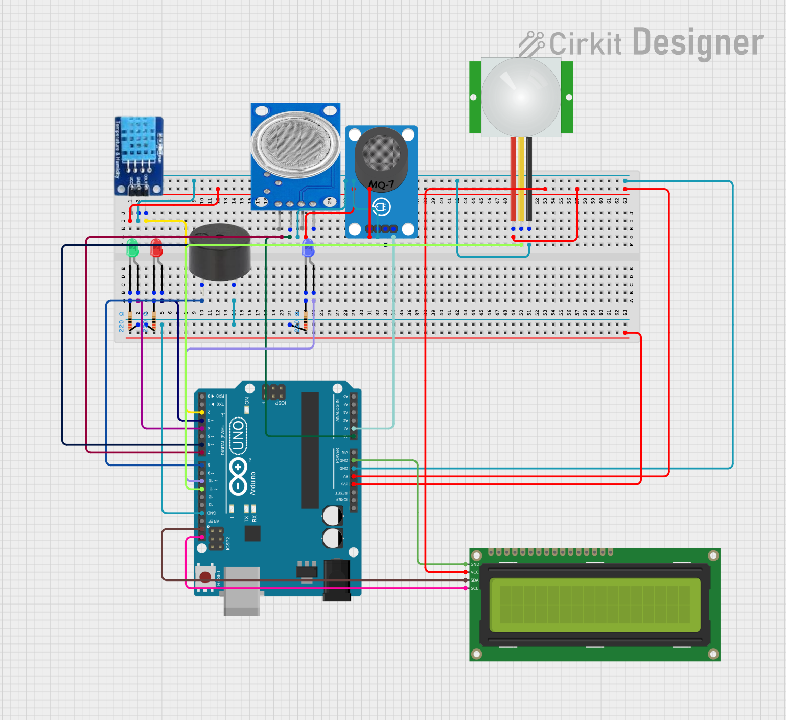
This circuit is designed to monitor air quality using gas sensors (MQ-7 and MQ-135), a temperature and humidity sensor (DHT11), and a PIR sensor. The data is displayed on a 16x2 I2C LCD, and visual/auditory alerts are provided using LEDs and a buzzer. The circuit is controlled by an Arduino UNO microcontroller.
Component List
LED: Two Pin (green)
- Description: Green LED
- Pins: Cathode, Anode
Resistor (220 Ohms)
- Description: Resistor with 220 Ohms resistance
- Pins: Pin1, Pin2
Arduino UNO
- Description: Microcontroller board
- Pins: UNUSED, IOREF, Reset, 3.3V, 5V, GND, Vin, A0, A1, A2, A3, A4, A5, SCL, SDA, AREF, D13, D12, D11, D10, D9, D8, D7, D6, D5, D4, D3, D2, D1, D0
LED: Two Pin (red)
- Description: Red LED
- Pins: Cathode, Anode
Buzzer
- Description: Buzzer for auditory alerts
- Pins: PIN, GND
DHT11
- Description: Temperature and humidity sensor
- Pins: DATA, GND, VCC
MQ135
- Description: Gas sensor
- Pins: VCC, GND, A0, D0
MQ-7 Breakout
- Description: Gas sensor
- Pins: VCC, GND, DO, AO
16x2 I2C LCD
- Description: LCD display with I2C interface
- Pins: GND, VCC, SDA, SCL
LED: Two Pin (blue)
- Description: Blue LED
- Pins: Cathode, Anode
PIR sensor
- Description: Passive Infrared sensor
- Pins: VDD, SIG, GND
Wiring Details
LED: Two Pin (green)
- Anode connected to D4 on Arduino UNO
- Cathode connected to Pin2 of a 220 Ohm Resistor
Resistor (220 Ohms)
- Pin1 connected to GND on Arduino UNO
- Pin2 connected to Cathode of the green LED
Arduino UNO
- 5V connected to VCC of MQ-7 Breakout, PIR sensor, and 16x2 I2C LCD
- GND connected to GND of DHT11, MQ-7 Breakout, PIR sensor, and 16x2 I2C LCD
- D2 connected to DATA of DHT11
- D3 connected to Anode of the red LED
- D4 connected to Anode of the green LED
- D8 connected to PIN of the buzzer
- A0 connected to A0 of MQ135
- D10 connected to Anode of the blue LED
- D6 connected to DO of MQ-7 Breakout
- A1 connected to AO of MQ-7 Breakout
- D11 connected to SIG of PIR sensor
- SCL connected to SCL of 16x2 I2C LCD
- SDA connected to SDA of 16x2 I2C LCD
LED: Two Pin (red)
- Anode connected to D3 on Arduino UNO
- Cathode connected to Pin2 of a 220 Ohm Resistor
Buzzer
- PIN connected to D8 on Arduino UNO
- GND connected to Pin1 of a 220 Ohm Resistor
DHT11
- DATA connected to D2 on Arduino UNO
- GND connected to GND on Arduino UNO
- VCC connected to 5V on Arduino UNO
MQ135
- A0 connected to A0 on Arduino UNO
- GND connected to GND on Arduino UNO
- VCC connected to 5V on Arduino UNO
MQ-7 Breakout
- VCC connected to 5V on Arduino UNO
- GND connected to GND on Arduino UNO
- DO connected to D6 on Arduino UNO
- AO connected to A1 on Arduino UNO
16x2 I2C LCD
- GND connected to GND on Arduino UNO
- VCC connected to 5V on Arduino UNO
- SDA connected to SDA on Arduino UNO
- SCL connected to SCL on Arduino UNO
LED: Two Pin (blue)
- Anode connected to D10 on Arduino UNO
- Cathode connected to Pin2 of a 220 Ohm Resistor
PIR sensor
- VDD connected to 5V on Arduino UNO
- SIG connected to D11 on Arduino UNO
- GND connected to GND on Arduino UNO
Code Documentation
/*
  AnalogReadSerial

  Reads an analog input on pin 0, prints the result to the Serial Monitor.
  Graphical representation is available using Serial Plotter (Tools > Serial Plotter menu).
  Attach the center pin of a potentiometer to pin A0, and the outside pins to +5V and ground.

  This example code is in the public domain.

  https://www.arduino.cc/en/Tutorial/BuiltInExamples/AnalogReadSerial
*/

#include <DHT11.h>
#include <Wire.h>
#include <LiquidCrystal_I2C.h>

LiquidCrystal_I2C lcd(0x27,16 ,2);
// Define sensor pins
int mq7Pin = A0;  // MQ-7 analog sensor connected to A0
int mq135Pin = A1;  // MQ-135 analog sensor connected to A1
// DHT11 sensor settings

DHT11 dht11(2); // Create an instance of the DHT sensorlcd.begin();

// Define other pins for LEDs and buzzer
int redLED = 3;
int greenLED = 4;
int buzzer = 8;

void setup() {

  lcd.init();                      // initialize the lcd
  lcd.init();

  lcd.backlight();

  // Start serial communication
  Serial.begin(9600);
  delay(2000);  // Wait for 2 seconds
  pinMode(redLED, OUTPUT);
  pinMode(greenLED, OUTPUT);
  pinMode(buzzer, OUTPUT);
}

void loop() {

  // Read gas sensor values (analog)
  int mq7Value = analogRead(mq7Pin);
  int mq135Value = analogRead(mq135Pin);

   // Read temperature and humidity from DHT11
  int temperature = 0;
  int humidity = 0;      // Humidity in percentage
  int result = dht11.readTemperatureHumidity(temperature, humidity);
  if (result == 0) {
        Serial.print("Temperature: ");
        Serial.print(temperature);
        Serial.print(" °C\tHumidity: ");
        Serial.print(humidity);
        Serial.println(" %");
    } else {
        // Print error message based on the error code.
        Serial.println(DHT11::getErrorString(result));
    }
  // Print values to serial for ESP8266


  // Simulate an alert if gas levels are too high (you can change these threshold values)
  if (mq7Value > 400 || mq135Value > 400) {
    digitalWrite(redLED, HIGH);  // Turn on red LED
    digitalWrite(greenLED, LOW); // Turn off green LED
    digitalWrite(buzzer, HIGH);
    lcd.clear();
    lcd.setCursor(0, 0);
    lcd.print("Dangerous gases");
    lcd.setCursor(0, 1);
    lcd.print("Detected!"); // Turn on buzzer
  } else {
    digitalWrite(redLED, LOW);   // Turn off red LED
    digitalWrite(greenLED, HIGH);// Turn on green LED
    digitalWrite(buzzer, LOW);
    lcd.clear();
    lcd.setCursor(0, 0);
    lcd.print("Air is clean");   // Turn off buzzer
  }
  Serial.print("MQ7: ");
  Serial.print(mq7Value);
  Serial.print(" | MQ135: ");
  Serial.println(mq135Value);
  digitalWrite(greenLED, HIGH);

  // int dangerousThreshold = 400; // Set a