Arduino UNO Based Keypad Door Lock System with LCD Feedback and Relay Control
Circuit Documentation
Summary
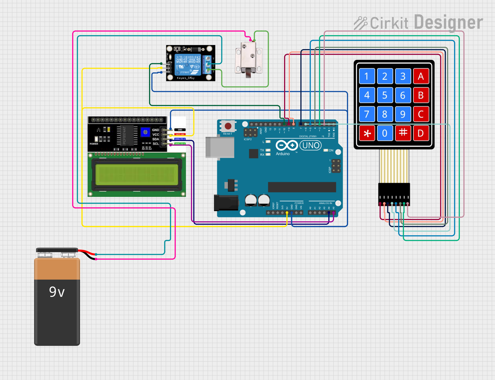
This circuit is designed to function as a door lock system, utilizing a 4x4 membrane matrix keypad for input, an LCD I2C display for user feedback, a relay module to control the locking mechanism, and an Arduino UNO as the central microcontroller. The system allows a user to input a password via the keypad, which is then displayed on the LCD. If the entered password matches the predefined password, the relay is activated, which in turn can unlock a door by controlling a 12V solenoid lock. The system is powered by a 9V battery.
Component List
Arduino UNO
- Microcontroller board based on the ATmega328P
- Provides digital I/O pins, analog inputs, and various power outputs
LCD I2C Display
- Alphanumeric liquid crystal display with I2C communication interface
- Used to display user prompts and feedback
Relay Module 1 Channel
- Electromechanical switch controlled by a digital signal from the Arduino
- Used to activate the solenoid lock
4X4 Membrane Matrix Keypad
- Input device with 16 buttons arranged in a 4x4 grid
- Used for entering the password
12V Solenoid Lock
- Electromechanical locking mechanism
- Engages and disengages the lock when powered
9V Battery
- Power source for the relay module and solenoid lock
Wiring Details
Arduino UNO
5VandGNDpins provide power to the LCD display and relay moduleA4 (SDA)andA5 (SCL)pins are connected to the corresponding SDA and SCL pins on the LCD for I2C communication- Digital pins
D2toD10are used to interface with the keypad and control the relay
LCD I2C Display
VCCconnected to5Von ArduinoGNDconnected toGNDon ArduinoSDAconnected toA4on ArduinoSCLconnected toA5on Arduino
Relay Module 1 Channel
S(signal) connected toD10on Arduino5VandGNDconnected to corresponding power pins on ArduinoCOM(common) connected to+on the 9V batteryNO(normally open) connected toVCCon the solenoid lock
4X4 Membrane Matrix Keypad
R1toR4connected to digital pinsD9toD6on ArduinoC1toC4connected to digital pinsD5toD2on Arduino
12V Solenoid Lock
VCCconnected toNOon the relay moduleGNDconnected to-on the 9V battery
9V Battery
+connected toCOMon the relay module-connected toGNDon the solenoid lock
Documented Code
/*
 * Door Lock System using 4x4 Keypad, LCD, and Relay
 * This code reads input from a 4x4 keypad, displays it on an LCD using I2C,
 * and checks if the entered code matches a predefined password to
 * unlock the door by activating a relay. Feedback is provided on incorrect
 * entry, and blocking delays are prevented.
 * Password: 1234
 */

#include <Keypad.h>
#include <Wire.h>
#include <LiquidCrystal_I2C.h>

const byte ROWS = 4; // Four rows
const byte COLS = 4; // Four columns
char keys[ROWS][COLS] = {
  {'1','2','3','A'},
  {'4','5','6','B'},
  {'7','8','9','C'},
  {'*','0','#','D'}
};
byte rowPins[ROWS] = {9, 8, 7, 6}; // Connect to the row pinouts of the keypad
byte colPins[COLS] = {5, 4, 3, 2}; // Connect to the column pinouts of the keypad

Keypad keypad = Keypad(makeKeymap(keys), rowPins, colPins, ROWS, COLS);

LiquidCrystal_I2C lcd(0x27, 16, 2); // Set the LCD address to 0x27 for a 16 chars and 2 line display

const int relayPin = 10; // Pin connected to the relay
String password = "1234";
String input = "";
unsigned long lastInteraction = 0;
const unsigned long timeout = 3000; // 3 seconds timeout for feedback

void setup() {
  pinMode(relayPin, OUTPUT);
  digitalWrite(relayPin, LOW); // Ensure relay is off initially
  lcd.begin(16,2);
  lcd.backlight();
  lcd.print("Enter Password:");
}

void loop() {
  char key = keypad.getKey();
  if (key) {
    lastInteraction = millis();
    if (key == '#') {
      if (input == password) {
        lcd.clear();
        lcd.print("Access Granted");
        digitalWrite(relayPin, HIGH); // Activate relay
        delay(5000); // Keep relay on for 5 seconds
        digitalWrite(relayPin, LOW); // Deactivate relay
      } else {
        lcd.clear();
        lcd.print("Access Denied");
      }
      input = "";
    } else if (key == '*') {
      input = "";
      lcd.clear();
      lcd.print("Enter Password:");
    } else {
      input += key;
      lcd.setCursor(0, 1);
      lcd.print(input);
    }
  }
  if (millis() - lastInteraction > timeout && input != "") {
    lcd.clear();
    lcd.print("Enter Password:");
    input = "";
  }
}
This code is responsible for the operation of the door lock system. It initializes the keypad and LCD, reads input from the keypad, compares the input to a predefined password, and controls the relay to lock or unlock the door accordingly. The LCD provides feedback to the user, prompting for the password and indicating whether access is granted or denied.