Cirkit Designer
Your all-in-one circuit design IDE
Home /
Project Documentation
Arduino Mega 2560-Controlled Fire Safety Robot with Automated Water Pump and Motion Actuators
Circuit Documentation
Summary
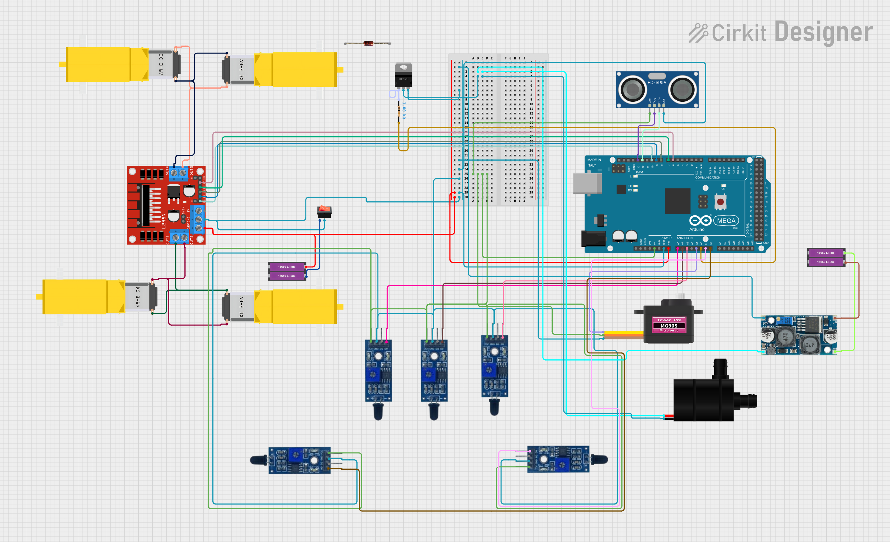
This circuit is designed to interface various sensors, actuators, and power management components with an Arduino Mega 2560 microcontroller. The circuit includes flame sensors for detecting fire or heat sources, a servomotor for actuation, a water pump for fluid movement, gearmotors for mechanical motion, an ultrasonic sensor for distance measurement, and power management components including a voltage regulator and batteries. The circuit is controlled by the Arduino Mega 2560, which is programmed to interact with the connected components based on the inputs from sensors and predefined logic.
Component List
Arduino Mega 2560
- Microcontroller board based on the ATmega2560
- It has 54 digital input/output pins (of which 15 can be used as PWM outputs), 16 analog inputs, 4 UARTs (hardware serial ports), a 16 MHz crystal oscillator, a USB connection, a power jack, an ICSP header, and a reset button.
Flame Sensor
- Sensor for detecting fire and heat
- Typically includes a digital output (D0) and an analog output (A0)
Servomotor MG90S
- Small and lightweight servo for precise control
- Operates on a control signal and provides positional feedback
Water Pump
- Electric pump for moving water or other fluids
- Requires power and ground connections
XL6009 Voltage Regulator
- A DC-DC converter that steps up voltage from a lower voltage to a higher one
- Has input and output connections for voltage regulation
18650 Li-ion Battery x 2
- Rechargeable lithium-ion battery cells
- Provides power to the circuit
L298N DC Motor Driver
- A dual H-bridge motor driver that can drive two DC motors or one stepper motor
- Has inputs for motor control signals and outputs for motor connections
Gearmotor DC / Motorreductor
- A DC motor with a gearbox for increased torque
- Has two connections for motor power
Rocker Switch
- A simple on/off switch to control power flow
- Has input and output connections
TIP120 Hi-Current Darlington Transistor
- A transistor that can control high current loads
- Has base, collector, and emitter pins
12V Zener Diode
- A diode that allows current to flow in one direction and blocks reverse current up to a certain voltage
- Has an anode and cathode
Resistor
- A passive component that resists the flow of electric current
- Used for current limiting or voltage division
HC-SR04 Ultrasonic Sensor
- A sensor for measuring distance using ultrasonic waves
- Has VCC, TRIG, ECHO, and GND pins
Wiring Details
Arduino Mega 2560
- 5V: Connected to VCC of all Flame Sensors, Servomotor MG90S, and HC-SR04 Ultrasonic Sensor
- GND: Common ground with Water Pump, Servomotor MG90S, HC-SR04 Ultrasonic Sensor, Flame Sensors, L298N DC Motor Driver, and Rocker Switch
- VIN: Connected to the positive terminal of the 18650 Li-ion Battery x 2
- A0-A7: Analog inputs connected to Flame Sensors and Servomotor MG90S
- D6-D13 PWM: Digital outputs connected to L298N DC Motor Driver and HC-SR04 Ultrasonic Sensor
Flame Sensors
- VCC: Connected to 5V on Arduino Mega 2560
- GND: Common ground with Arduino Mega 2560
- A0: Analog output connected to analog inputs on Arduino Mega 2560
Servomotor MG90S
- SIG: Signal connected to A4 on Arduino Mega 2560
- VCC: Connected to 5V on Arduino Mega 2560
- GND: Common ground with Arduino Mega 2560
Water Pump
- VCC: Connected to OUT + on XL6009 Voltage Regulator
- GND: Connected to COLLECTOR on TIP120 Hi-Current Darlington Transistor
XL6009 Voltage Regulator
- IN +: Connected to the positive terminal of the 18650 Li-ion Battery x 2
- IN -: Connected to the negative terminal of the 18650 Li-ion Battery x 2
- OUT +: Connected to VCC on Water Pump
- OUT -: Common ground with TIP120 Hi-Current Darlington Transistor
18650 Li-ion Battery x 2
- +: Connected to VIN on Arduino Mega 2560 and IN + on XL6009 Voltage Regulator
- -: Connected to input on Rocker Switch and IN - on XL6009 Voltage Regulator
L298N DC Motor Driver
- 12V: Connected to the positive terminal of the 18650 Li-ion Battery x 2
- GND: Common ground with Arduino Mega 2560
- IN1-IN4: Control inputs connected to D6-D9 PWM on Arduino Mega 2560
- OUT1-OUT4: Outputs connected to Gearmotor DC / Motorreductor
Gearmotor DC / Motorreductor
- Pin1 and Pin2: Connected to OUT1-OUT4 on L298N DC Motor Driver
Rocker Switch
- Input: Connected to the negative terminal of the 18650 Li-ion Battery x 2
- Output: Common ground with Arduino Mega 2560
TIP120 Hi-Current Darlington Transistor
- BASE: Connected to pin1 on Resistor
- COLLECTOR: Connected to GND on Water Pump
- EMITTER: Common ground with XL6009 Voltage Regulator
Resistor
- Pin1: Connected to BASE on TIP120 Hi-Current Darlington Transistor
- Pin2: Connected to A5 on Arduino Mega 2560
HC-SR04 Ultrasonic Sensor
- VCC: Connected to 5V on Arduino Mega 2560
- TRIG: Connected to D13 PWM on Arduino Mega 2560
- ECHO: Connected to D12 PWM on Arduino Mega 2560
- GND: Common ground with Arduino Mega 2560
Documented Code
Arduino Mega 2560 - sketch.ino
void setup() {
  // put your setup code here, to run once:

}

void loop() {
  // put your main code here, to run repeatedly:

}
Arduino Mega 2560 - documentation.txt
(No additional documentation provided for the code)