Arduino Mega 2560 Controlled TFT Touchscreen Interface with 4-Channel Relay Automation
Circuit Documentation
Summary
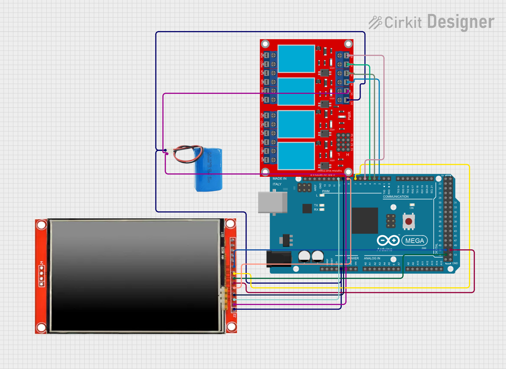
This circuit integrates an Arduino Mega 2560 microcontroller with an LCD TFT screen (ILI9488 HD), a 4-channel relay module, and a 5V power supply (battery). The Arduino Mega 2560 controls the LCD display to show interactive buttons and manages the state of the relays based on user input on the touchscreen. The relays can be toggled on and off to control external devices or circuits. The 5V battery provides power to the entire circuit.
Component List
Arduino Mega 2560
- Microcontroller board based on the ATmega2560
- Offers 54 digital input/output pins (of which 15 can be used as PWM outputs), 16 analog inputs, 4 UARTs (hardware serial ports), a 16 MHz crystal oscillator, a USB connection, a power jack, an ICSP header, and a reset button.
LCD TFT screen ILI9488 HD
- A color display with a resolution of 320x480 pixels
- It has an integrated ILI9488 HD controller and supports a 16-bit data interface.
4-channel relay module
- A module with four relays that can be individually controlled
- Each relay has a normally open (N.O.) and a normally closed (N.C.) contact, along with a common (COM) terminal.
5V battery
- A power source for the circuit
- Provides a stable 5V output to power the components.
Wiring Details
Arduino Mega 2560
5Vconnected to LCD TFT screen VCC, 4-channel relay module VCC+, and 5V battery positive.GNDconnected to LCD TFT screen GND, 4-channel relay module VCC- (GND), and 5V battery negative.D2 PWMconnected to 4-channel relay module IN 1.D3 PWMconnected to 4-channel relay module IN 2.D4 PWMconnected to 4-channel relay module IN 3.D5 PWMconnected to 4-channel relay module IN 4.D7 PWMconnected to LCD TFT screen BL (backlight).D8 PWMconnected to LCD TFT screen D/C (data/command).D9 PWMconnected to LCD TFT screen RST (reset).D10 PWMconnected to LCD TFT screen CS (chip select).D52connected to LCD TFT screen SCK (serial clock).D50connected to LCD TFT screen SDO (MISO - Master In Slave Out).D51connected to LCD TFT screen SDI (MOSI - Master Out Slave In).
LCD TFT screen ILI9488 HD
VCC (3.3~5V)connected to Arduino Mega 2560 5V and 5V battery positive.GNDconnected to Arduino Mega 2560 GND and 5V battery negative.BLconnected to Arduino Mega 2560 D7 PWM.D/Cconnected to Arduino Mega 2560 D8 PWM.RSTconnected to Arduino Mega 2560 D9 PWM.CSconnected to Arduino Mega 2560 D10 PWM.SCKconnected to Arduino Mega 2560 D52.SDO(MISO)connected to Arduino Mega 2560 D50.SDI(MOSI)connected to Arduino Mega 2560 D51.
4-channel relay module
VCC+connected to Arduino Mega 2560 5V and 5V battery positive.VCC- (GND)connected to Arduino Mega 2560 GND and 5V battery negative.IN 1connected to Arduino Mega 2560 D2 PWM.IN 2connected to Arduino Mega 2560 D3 PWM.IN 3connected to Arduino Mega 2560 D4 PWM.IN 4connected to Arduino Mega 2560 D5 PWM.
5V battery
positiveconnected to Arduino Mega 2560 5V, LCD TFT screen VCC, and 4-channel relay module VCC+.negativeconnected to Arduino Mega 2560 GND, LCD TFT screen GND, and 4-channel relay module VCC- (GND).
Documented Code
#include <Adafruit_ILI9341.h>
#include <TouchScreen.h>
#include <Adafruit_GFX.h>

/*
 * This Arduino Sketch sets up an ILI9488 TFT LCD display, a Mega 2560 board,
 * and a 4-channel relay module. The code displays four buttons on the LCD,
 * each controlling one of the four relays. Pressing a button toggles the
 * corresponding relay on or off.
 */

// Pin definitions
#define TFT_CS 10
#define TFT_RST 9
#define TFT_DC 8
#define TFT_MOSI 51
#define TFT_CLK 52
#define TFT_MISO 50
#define TFT_BL 7
#define RELAY1 2
#define RELAY2 3
#define RELAY3 4
#define RELAY4 5

// Touch screen pins
#define YP A3  // must be an analog pin, use "An" notation!
#define XM A2  // must be an analog pin, use "An" notation!
#define YM 9   // can be a digital pin
#define XP 8   // can be a digital pin

// Touch screen calibration values
#define TS_MINX 100
#define TS_MINY 120
#define TS_MAXX 940
#define TS_MAXY 920

// Create display and touch screen objects
Adafruit_ILI9341 tft = Adafruit_ILI9341(TFT_CS, TFT_DC, TFT_RST);
TouchScreen ts = TouchScreen(XP, YP, XM, YM, 300);

// Button coordinates
#define BUTTON_X 60
#define BUTTON_Y 40
#define BUTTON_W 120
#define BUTTON_H 60
#define BUTTON_SPACING_X 60
#define BUTTON_SPACING_Y 80

// Button states
bool relayState[4] = {false, false, false, false};

void setup() {
  // Initialize serial communication
  Serial.begin(9600);

  // Initialize the display
  tft.begin();
  tft.setRotation(1);
  tft.fillScreen(ILI9341_BLACK);

  // Initialize relay pins
  pinMode(RELAY1, OUTPUT);
  pinMode(RELAY2, OUTPUT);
  pinMode(RELAY3, OUTPUT);
  pinMode(RELAY4, OUTPUT);

  // Draw initial buttons
  drawButtons();
}

void loop() {
  // Check for touch
  TSPoint p = ts.getPoint();
  if (p.z > ts.pressureThreshhold) {
    // Map touch coordinates
    int x = map(p.x, TS_MINX, TS_MAXX, 0, tft.width());
    int y = map(p.y, TS_MINY, TS_MAXY, 0, tft.height());

    // Check which button was pressed
    for (int i = 0; i < 4; i++) {
      if (x > BUTTON_X && x < BUTTON_X + BUTTON_W &&
          y > BUTTON_Y + i * BUTTON_SPACING_Y &&
          y < BUTTON_Y + i * BUTTON_SPACING_Y + BUTTON_H) {
        // Toggle relay state
        relayState[i] = !relayState[i];
        digitalWrite(RELAY1 + i, relayState[i] ? HIGH : LOW);
        // Redraw button
        drawButton(i);
      }
    }
  }
}

void drawButtons() {
  for (int i = 0; i < 4; i++) {
    drawButton(i);
  }
}

void drawButton(int i) {
  tft.fillRect(BUTTON_X, BUTTON_Y + i * BUTTON_SPACING_Y, BUTTON_W, BUTTON_H,
               relayState[i] ? ILI9341_GREEN : ILI9341_RED);
  tft.drawRect(BUTTON_X, BUTTON_Y + i * BUTTON_SPACING_Y, BUTTON_W, BUTTON_H,
               ILI9341_WHITE);
  tft.setCursor(BUTTON_X + 10, BUTTON_Y + i * BUTTON_SPACING_Y + 20);
  tft.setTextColor(ILI9341_WHITE);
  tft.setTextSize(2);
  tft.print("Relay ");
  tft.print(i + 1);
}
The code provided is an Arduino sketch that initializes the ILI9488 TFT LCD display and the 4-channel relay module. It sets up a simple graphical user interface with buttons on the display that, when pressed, toggle the state of the corresponding relay. The touch screen is used to detect button presses, and the relay states are updated accordingly. The code includes functions for drawing the buttons on the display and handling the touch events.