
Arduino Mega 2560 Based Automatic Smoke Detection and Alert System with Solar Charging
View and Edit Project In Cirkit Designer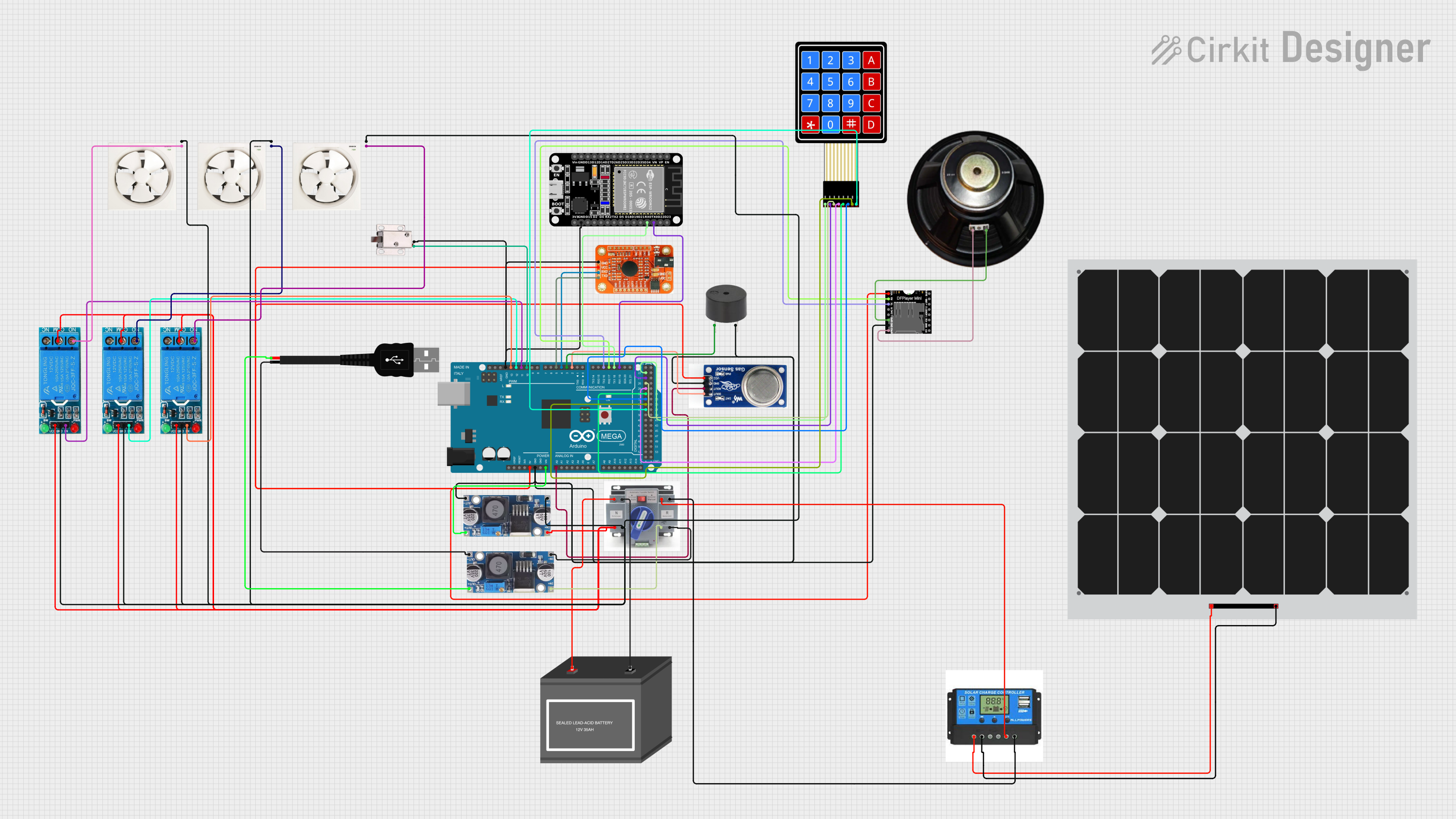
Circuit Documentation
Summary
This circuit is designed for an automatic system that interacts with various sensors and modules to perform specific actions based on environmental conditions and inputs. The system is capable of detecting smoke or gas using an MQ2 sensor, controlling power to an exhaust fan and a solenoid lock, and providing audio feedback through a buzzer and a DFPlayer Mini module. It also includes a voice recognition module for receiving voice commands and an ESP32 microcontroller for additional functionalities. The circuit is powered by a 12V battery, which is charged by a solar panel through a charge controller. An ATS (Automatic Transfer Switch) is used to switch between the battery and solar power. The main control unit is an Arduino Mega 2560, which manages the inputs and outputs and communicates with the ESP32 and other modules.
Component List
Power Sources
- 12V Battery (mini): Provides the main power supply for the circuit.
- Solar Panel: Charges the battery through the charge controller during daylight.
Sensors and Modules
- MQ2 Gas Sensor: Detects the presence of gases such as LPG, propane, methane, alcohol, smoke, and others.
- Voice Recognition Module: Receives and processes voice commands.
- DFPlayer Mini: A small and low-cost MP3 module that can directly play MP3 files stored on a USB or TF card.
- ESP32 (30 pin): A powerful microcontroller with Wi-Fi and Bluetooth capabilities for additional functionalities.
Actuators
- Exhaust Fan 12": Ventilates the area when activated by a relay.
- 12V Solenoid Lock: Electromechanical lock controlled by the Arduino.
- Speaker: Outputs audio signals from the DFPlayer Mini.
Control and Conversion
- Arduino Mega 2560: The main microcontroller board that controls the system.
- Step Down Buck Converter: Converts higher voltage to a lower voltage to power USB devices.
- ATS (Automatic Transfer Switch): Automatically switches between solar panel and battery power.
- Charge Controller: Manages the charging of the battery from the solar panel and protects against overcharging.
- 12V Single Channel Relay: Electrically operated switches that control the power to the exhaust fans.
Input Devices
- 4X4 Membrane Matrix Keypad: Allows user input through a simple interface.
Indicators
- Buzzer: Provides audible alerts or feedback.
Wiring Details
Power Distribution
- 12V Battery (mini): Powers the ATS and the Step Down Buck Converter.
- Solar Panel: Connects to the Charge Controller to charge the battery.
Sensors and Modules
MQ2 Gas Sensor:
D0connected to Arduino MegaD2 PWM.A0connected to Arduino MegaA0.GNDconnected to common ground.VCCconnected to Arduino Mega5V.
Voice Recognition Module:
GNDconnected to common ground.VCCconnected to Arduino Mega5V.RDXconnected to Arduino MegaD4 PWM.RTXconnected to Arduino MegaD5 PWM.
DFPlayer Mini:
GNDconnected to common ground.VCCconnected to Arduino Mega5V.RXconnected to Arduino MegaD16 PWM/TX2.TXconnected to Arduino MegaD17 PWM/RX2.SPK1andSPK2connected to Speaker.
ESP32 (30 pin):
TX0connected to Arduino MegaD19/RX1.RX0connected to Arduino MegaD18/TX1.GNDconnected to common ground.
Actuators
Exhaust Fan 12":
Liveconnected toNOon respective 12V Single Channel Relays.Neutralconnected to common ground.
12V Solenoid Lock:
VCCconnected to Arduino MegaD10 PWM.GNDconnected to common ground.
Control and Conversion
Arduino Mega 2560:
GNDconnected to common ground.5Vconnected toVCCon various components.VINconnected to the output of the Step Down Buck Converter.
Step Down Buck Converter:
IN +andIN - GNDconnected to ATS.OUT +andOUT - GNDconnected to USB male 2 pin connection.
ATS:
+and-connected to 12V Battery (mini).+and-connected to various components and relays.
Charge Controller:
Solar PositiveandSolar Negativeconnected to Solar Panel.Load PositiveandLoad Negativeconnected to ATS.
12V Single Channel Relay:
INconnected to respective Arduino Mega PWM pins (D11 PWM,D12 PWM,D13 PWM).GNDconnected to common ground.VCCconnected to ATS+.COMconnected to ATS+.NOconnected to respective Exhaust FanLive.
Input Devices
- 4X4 Membrane Matrix Keypad:
R1toR4andC1toC4connected to respective Arduino Mega pins (D22toD36).
Indicators
- Buzzer:
PINconnected to Arduino MegaD3 PWM.GNDconnected to common ground.
Documented Code
/*
 * This Arduino sketch is designed for an automatic system that opens a solenoid
 * lock and activates a buzzer when the MQ2 sensor detects smoke or gas. The
 * system also includes a DFPlayer Mini for audio output, a voice recognition
 * module, and an ESP32 for additional functionalities. The circuit is powered
 * by a 12V battery and a solar panel with a charge controller.
 */

#include <SoftwareSerial.h>

// Pin definitions
const int mq2DigitalPin = 2;
const int mq2AnalogPin = A0;
const int solenoidPin = 10;
const int buzzerPin = 3;
const int relay1Pin = 11;
const int relay2Pin = 12;
const int relay3Pin = 13;

// DFPlayer Mini
SoftwareSerial myDFPlayer(16, 17); // RX, TX

void setup() {
  // Initialize serial communication
  Serial.begin(9600);
  myDFPlayer.begin(9600);

  // Initialize pins
  pinMode(mq2DigitalPin, INPUT);
  pinMode(mq2AnalogPin, INPUT);
  pinMode(solenoidPin, OUTPUT);
  pinMode(buzzerPin, OUTPUT);
  pinMode(relay1Pin, OUTPUT);
  pinMode(relay2Pin, OUTPUT);
  pinMode(relay3Pin, OUTPUT);

  // Initial states
  digitalWrite(solenoidPin, LOW);
  digitalWrite(buzzerPin, LOW);
  digitalWrite(relay1Pin, LOW);
  digitalWrite(relay2Pin, LOW);
  digitalWrite(relay3Pin, LOW);
}

void loop() {
  // Read MQ2 sensor
  int mq2DigitalValue = digitalRead(mq2DigitalPin);
  int mq2AnalogValue = analogRead(mq2AnalogPin);

  // Check for smoke or gas
  if (mq2DigitalValue == HIGH || mq2AnalogValue > 300) {
    // Activate solenoid lock and buzzer
    digitalWrite(solenoidPin, HIGH);
    digitalWrite(buzzerPin, HIGH);
    delay(5000); // Keep activated for 5 seconds
    digitalWrite(solenoidPin, LOW);
    digitalWrite(buzzerPin, LOW);
  }

  // Add any additional functionalities here
}
Filename: sketch.ino