Cirkit Designer
Your all-in-one circuit design IDE
Home /
Project Documentation
Arduino 101 Based IR Sensor Array with I2C LCD Display
Circuit Documentation
Summary of the Circuit
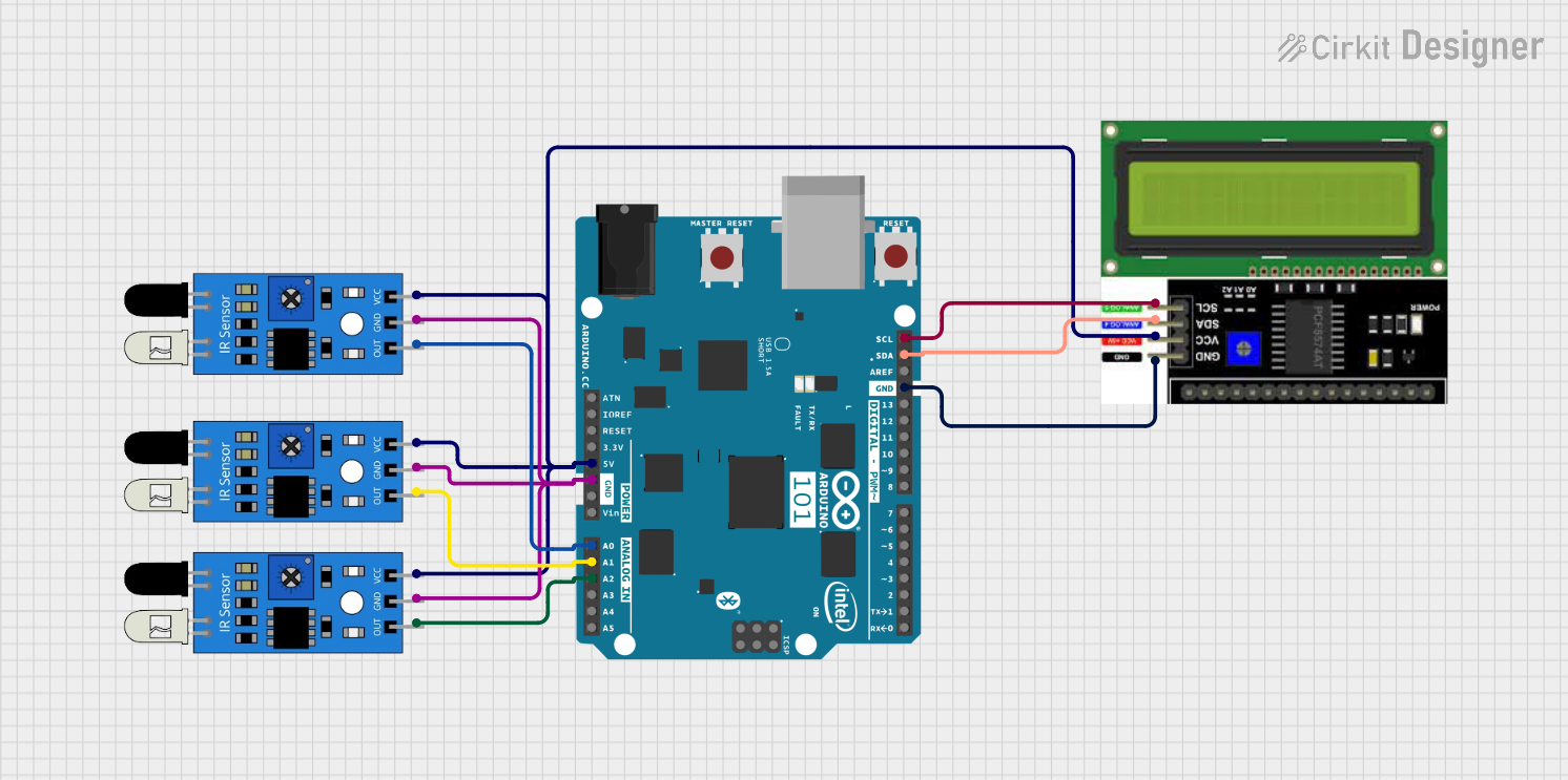
This circuit is designed to interface an Arduino 101 microcontroller with multiple IR sensors and an LCD I2C display. The Arduino 101 serves as the central processing unit, reading inputs from the IR sensors and displaying relevant information on the LCD. The IR sensors are used to detect the presence or absence of objects, and the LCD display provides a user interface to display the sensor readings or other messages.
Component List
Arduino 101
- Description: A microcontroller board based on the Intel Curie module, designed for building IoT applications. It has a rich set of I/O interfaces.
- Purpose: Acts as the central processing unit for the circuit, reading sensor data and controlling the LCD display.
IR Sensors
- Description: Infrared sensors that detect object presence and distance.
- Purpose: To provide input signals to the Arduino based on object detection.
LCD I2C Display
- Description: A liquid crystal display that uses the I2C communication protocol.
- Purpose: To display information such as sensor readings and status messages.
Wiring Details
Arduino 101
- A5/SCL: Connected to SCL pin of the LCD I2C Display for I2C communication.
- A4/SDA: Connected to SDA pin of the LCD I2C Display for I2C communication.
- GND: Connected to GND pins of the IR sensors and the LCD I2C Display to provide a common ground.
- 5V: Provides power to the VCC pins of the IR sensors and the VCC pin of the LCD I2C Display.
- A0: Receives the output signal from one of the IR sensors.
- A1: Receives the output signal from another IR sensor.
- A2: Receives the output signal from the third IR sensor.
IR Sensors
- out: Each sensor's output pin is connected to a separate analog input on the Arduino (A0, A1, A2).
- gnd: Ground pins of all sensors are connected to the Arduino's GND.
- vcc: Power pins of all sensors are connected to the Arduino's 5V output.
LCD I2C Display
- SCL: Connected to A5/SCL on the Arduino for I2C communication.
- SDA: Connected to A4/SDA on the Arduino for I2C communication.
- GND: Connected to the Arduino's GND.
- VCC: Powered by the Arduino's 5V output.
Documented Code
Since no code was provided, this section is left blank. The code for this circuit would typically include initialization of the I2C communication for the LCD display, reading of the IR sensor outputs, and logic for displaying the sensor readings on the LCD.