
Circuit Documentation
Summary
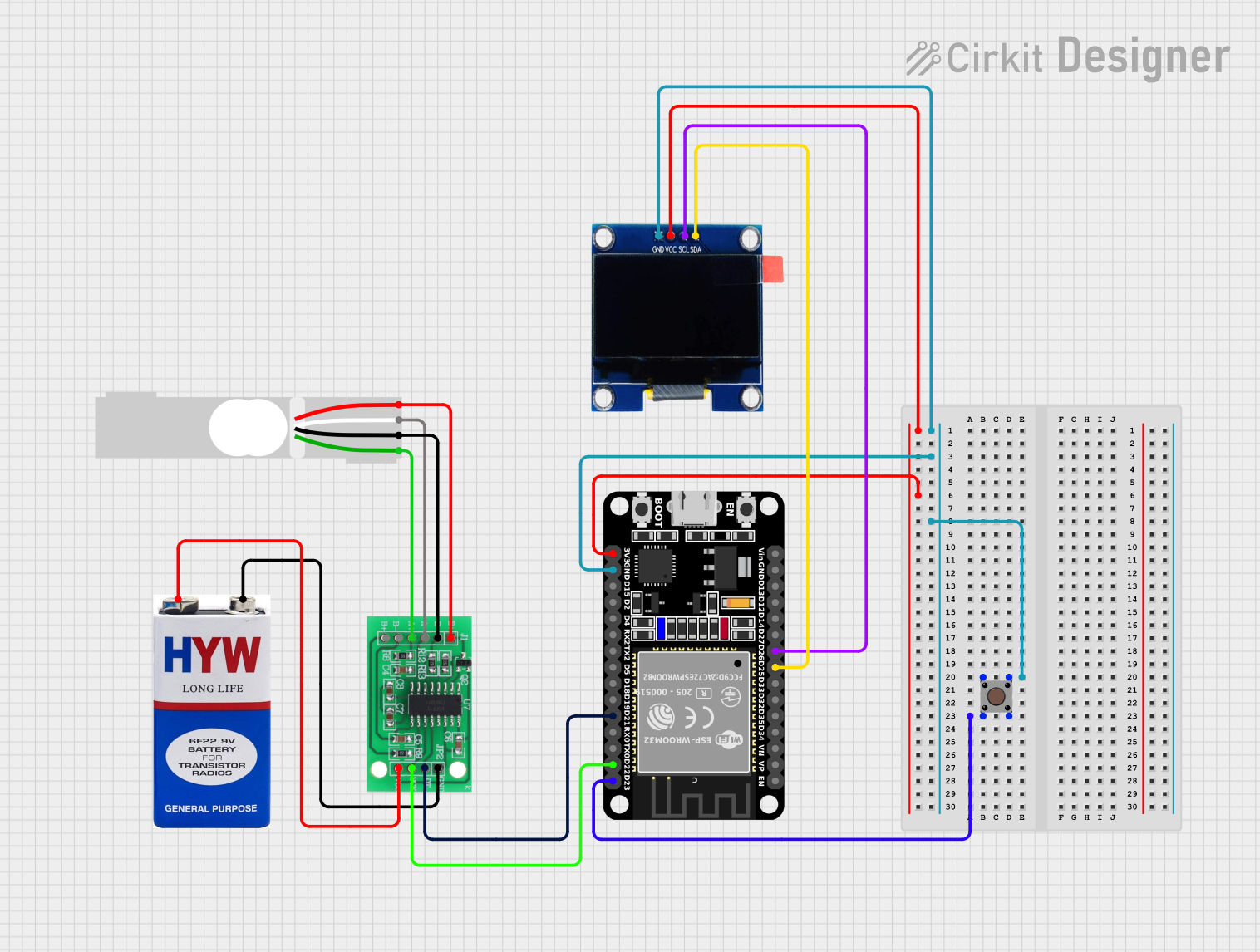
This circuit integrates various components to perform a specific function. It includes an ESP32 microcontroller, a pushbutton, a 9V battery, an HX711 bridge sensor interface, a load cell, and an OLED display. The ESP32 serves as the central processing unit, interfacing with the OLED display for user interaction and the HX711 for sensor data acquisition. The pushbutton provides user input, while the 9V battery supplies power to the circuit. The load cell is connected to the HX711, which amplifies and digitizes the analog signal from the load cell for the ESP32 to process.
Component List
ESP32 (30 pin)
- A microcontroller with WiFi and Bluetooth capabilities, featuring a variety of digital and analog pins for interfacing with peripherals.
Pushbutton
- A simple switch mechanism for control or input.
9V Battery
- A standard 9-volt battery used to provide power to the circuit.
HX711 - Bridge Sensor Interface
- A precision 24-bit analog-to-digital converter (ADC) designed for weigh scales and industrial control applications to interface directly with a bridge sensor.
Load Cell - Red/white/black/green
- A transducer that converts force into an electrical signal, used in conjunction with the HX711 for weight measurement.
OLED 1.3"
- A small organic light-emitting diode display for visual output.
Wiring Details
ESP32 (30 pin)
- GND: Connected to the ground plane.
- 3V3: Powers the OLED display.
- D23: Connected to the pushbutton (input).
- D25: Connected to the SDA pin of the OLED display.
- D26: Connected to the SCL pin of the OLED display.
- D21: Connected to the DATA (OUT) pin of the HX711.
- D22: Connected to the SCK - CLOCK (IN) pin of the HX711.
Pushbutton
- Pin 3 (out): Connected to the ground plane.
- Pin 1 (in): Connected to the ground plane.
- Pin 4 (out): Connected to the D23 pin of the ESP32.
- Pin 2 (in): Connected to the D23 pin of the ESP32.
9V Battery
- +: Powers the HX711.
- -: Connected to the ground plane of the HX711.
HX711 - Bridge Sensor Interface
- E+: Connected to the E+ pin of the Load Cell.
- E-: Connected to the E- pin of the Load Cell.
- A-: Connected to the A- pin of the Load Cell.
- A+: Connected to the A+ pin of the Load Cell.
- GND - GROUND: Connected to the ground plane.
- DATA (OUT): Connected to the D21 pin of the ESP32.
- SCK - CLOCK (IN): Connected to the D22 pin of the ESP32.
- 3.3/3.5V Supply: Powered by the 9V battery.
Load Cell - Red/white/black/green
- E+: Connected to the E+ pin of the HX711.
- A-: Connected to the A- pin of the HX711.
- E-: Connected to the E- pin of the HX711.
- A+: Connected to the A+ pin of the HX711.
OLED 1.3"
- GND: Connected to the ground plane.
- VCC: Powered by the 3V3 pin of the ESP32.
- SCL: Connected to the D26 pin of the ESP32.
- SDA: Connected to the D25 pin of the ESP32.
Documented Code
Since no code was provided for the microcontrollers in the circuit, this section is currently empty. When code is available, it should be documented here with comments explaining the functionality and the connections to the circuit components.