Arduino Mega 2560 Based Environmental Monitoring System with GSM Reporting
Circuit Documentation
Summary
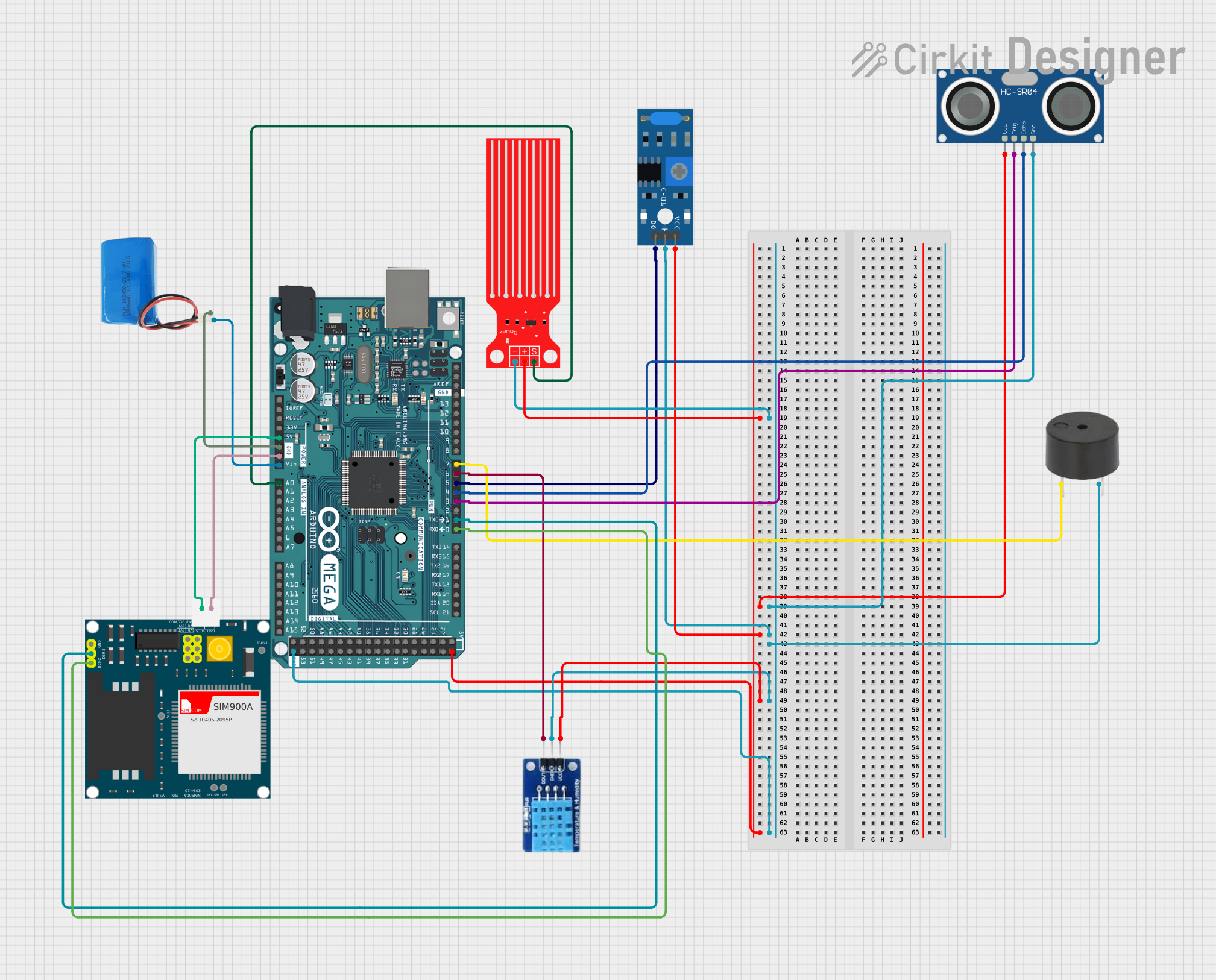
This document provides a detailed overview of a circuit that includes an Arduino Mega 2560 as the central microcontroller, interfaced with various sensors and modules including a SW-420 Vibration Sensor, HC-SR04 Ultrasonic Sensor, a buzzer, a Water Level Sensor, a DHT11 temperature and humidity sensor, and a SIM900A GSM module. The circuit is powered by a 5V battery. The purpose of this circuit is not explicitly stated, but it appears to be designed for environmental monitoring and alerting, with capabilities for measuring distance, vibration, water level, temperature, humidity, and for sending notifications via GSM.
Component List
Arduino Mega 2560
- Microcontroller board based on the ATmega2560
- Provides a large number of IO pins, including digital, analog, PWM, I2C, and UART
- Operates at 5V
SW-420 Vibration Sensor
- Detects vibrations and outputs a digital signal
HC-SR04 Ultrasonic Sensor
- Measures distances using ultrasonic waves
- Provides trigger (TRIG) and echo (ECHO) pins for interfacing
Buzzer
- Emits an audible alert when powered
Water Level Sensor
- Detects the level of water and outputs an analog signal
DHT11
- Sensor for measuring temperature and humidity
- Outputs data on a single digital pin
5V Battery
- Provides power to the circuit
SIM900A
- GSM/GPRS module for cellular communication
- Interfaces with the microcontroller via UART
Wiring Details
Arduino Mega 2560
5Vconnected to the VCC pins of the Water Level Sensor, HC-SR04 Ultrasonic Sensor, SW-420 Vibration Sensor, and DHT11GNDconnected to the Ground pins of the Water Level Sensor, HC-SR04 Ultrasonic Sensor, SW-420 Vibration Sensor, buzzer, and DHT11VINconnected to the positive terminal of the 5V batteryA0connected to the SIG pin of the Water Level SensorD0 RX0connected to the TXD pin of the SIM900AD1 TX0connected to the RXD pin of the SIM900AD3 PWMconnected to the TRIG pin of the HC-SR04 Ultrasonic SensorD4 PWMconnected to the ECHO pin of the HC-SR04 Ultrasonic SensorD5 PWMconnected to the Digital output pin of the SW-420 Vibration SensorD6 PWMconnected to the DATA pin of the DHT11D7 PWMconnected to the PIN of the buzzer
SW-420 Vibration Sensor
vccconnected to 5V from Arduino Mega 2560Groundconnected to GND from Arduino Mega 2560Digital outputconnected toD5 PWMon Arduino Mega 2560
HC-SR04 Ultrasonic Sensor
VCCconnected to 5V from Arduino Mega 2560TRIGconnected toD3 PWMon Arduino Mega 2560ECHOconnected toD4 PWMon Arduino Mega 2560GNDconnected to GND from Arduino Mega 2560
Buzzer
PINconnected toD7 PWMon Arduino Mega 2560GNDconnected to GND from Arduino Mega 2560
Water Level Sensor
SIGconnected toA0on Arduino Mega 2560VCCconnected to 5V from Arduino Mega 2560GNDconnected to GND from Arduino Mega 2560
DHT11
DATAconnected toD6 PWMon Arduino Mega 2560GNDconnected to GND from Arduino Mega 2560VCCconnected to 5V from Arduino Mega 2560
5V Battery
positiveconnected toVINon Arduino Mega 2560negativeconnected to GND from Arduino Mega 2560
SIM900A
5Vconnected to 5V from Arduino Mega 2560GNDconnected to GND from Arduino Mega 2560DB9-2 (TXD)connected toD0 RX0on Arduino Mega 2560DB9-3 (RXD)connected toD1 TX0on Arduino Mega 2560
Documented Code
Arduino Mega 2560 - sketch.ino
void setup() {
  // put your setup code here, to run once:

}

void loop() {
  // put your main code here, to run repeatedly:

}
Note: The provided code is a template and does not include any functionality. It needs to be populated with the logic to interact with the connected sensors and modules.