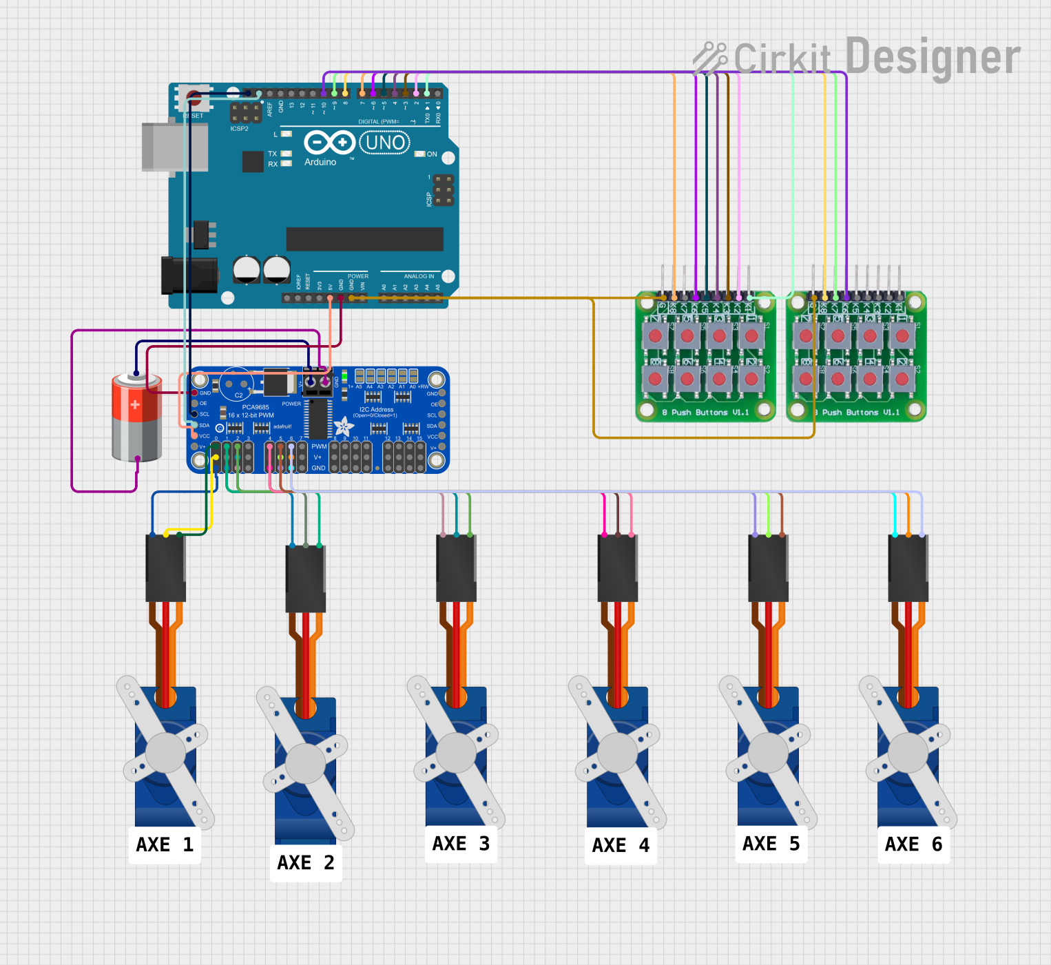
Arduino UNO Controlled Servo Motors with Button Interface

Circuit Documentation
Summary
This circuit is designed to control six Tower Pro SG90 servo motors using two 8 push button board PCBs. The control logic is implemented on an Arduino UNO microcontroller, which interfaces with an Adafruit PCA9685 PWM Servo Breakout board to drive the servos. The servos are powered by a 5V battery connected to the PWM Servo Breakout board. The Arduino UNO communicates with the PCA9685 board via I2C using the SDA and SCL lines. Each servo motor's position can be adjusted using the corresponding pair of buttons on the push button boards.
Component List
- Arduino UNO: A microcontroller board based on the ATmega328P, featuring digital and analog I/O pins.
- Adafruit PCA9685 PWM Servo Breakout: A 16-channel, 12-bit PWM Fm+ I2C-bus LED controller, used here to control servo motors.
- 5V Battery: Provides power to the Adafruit PCA9685 PWM Servo Breakout and the servo motors.
- Tower Pro SG90 Servo: Small and lightweight servo motors used for precise control of mechanical movement.
- 8 Push Button Board PCB: A board with 8 push buttons, used to provide input to the Arduino UNO for controlling the servo motors.
Wiring Details
Arduino UNO
- 5V: Connected to the VCC pin of the Adafruit PCA9685 PWM Servo Breakout.
- GND: Common ground with Adafruit PCA9685 PWM Servo Breakout and both 8 push button board PCBs.
- SCL: Connected to the SCL pin of the Adafruit PCA9685 PWM Servo Breakout for I2C communication.
- SDA: Connected to the SDA pin of the Adafruit PCA9685 PWM Servo Breakout for I2C communication.
- Digital Pins (D1-D10): Connected to the push button boards for receiving button press signals.
Adafruit PCA9685 PWM Servo Breakout
- VCC: Powered by the 5V output from the Arduino UNO.
- GND: Common ground with Arduino UNO and the servo motors.
- SCL: I2C clock line connected to the Arduino UNO.
- SDA: I2C data line connected to the Arduino UNO.
- PWRIN: Power input connected to the positive terminal of the 5V battery.
- PWM0-PWM6: PWM output channels connected to the signal lines of the Tower Pro SG90 servos.
- 5.0V: Power output to the Tower Pro SG90 servos.
- OE: Not connected in this circuit.
5V Battery
- +: Connected to the PWRIN pin of the Adafruit PCA9685 PWM Servo Breakout.
- -: Common ground with the Adafruit PCA9685 PWM Servo Breakout.
Tower Pro SG90 Servo
- Signal: Connected to the corresponding PWM output channel on the Adafruit PCA9685 PWM Servo Breakout.
- +5V: Powered by the 5.0V output from the Adafruit PCA9685 PWM Servo Breakout.
- GND: Common ground with the Adafruit PCA9685 PWM Servo Breakout.
8 Push Button Board PCB
- K1-K8: Each button pin is connected to a corresponding digital pin on the Arduino UNO.
- GROUND: Common ground with the Arduino UNO.
Documented Code
Arduino UNO Code
/*
 * This Arduino Sketch controls 6 servo motors using 12 buttons.
 * Each pair of buttons controls one servo motor, with one button
 * increasing the angle and the other decreasing it.
 */

#include <Wire.h>
#include <Adafruit_PWMServoDriver.h>

Adafruit_PWMServoDriver pwm = Adafruit_PWMServoDriver();

const int buttonPins[12] = {2, 3, 4, 5, 6, 7, 8, 9, 10, 11, 12, 13};
const int servoChannels[6] = {0, 1, 2, 4, 5, 6};
int servoAngles[6] = {90, 90, 90, 90, 90, 90};

void setup() {
  pwm.begin();
  pwm.setPWMFreq(60); // Analog servos run at ~60 Hz
  for (int i = 0; i < 12; i++) {
    pinMode(buttonPins[i], INPUT_PULLUP);
  }
}

void loop() {
  for (int i = 0; i < 6; i++) {
    if (digitalRead(buttonPins[i * 2]) == LOW) {
      servoAngles[i] = min(servoAngles[i] + 1, 180);
    }
    if (digitalRead(buttonPins[i * 2 + 1]) == LOW) {
      servoAngles[i] = max(servoAngles[i] - 1, 0);
    }
    pwm.setPWM(servoChannels[i], 0, angleToPulse(servoAngles[i]));
  }
  delay(15); // Small delay to debounce buttons
}

int angleToPulse(int angle) {
  return map(angle, 0, 180, 150, 600);
}
5V Battery Code
The 5V battery does not have associated code as it is a power supply component.
This documentation provides an overview of the circuit, including the purpose and wiring of each component, as well as the embedded code running on the Arduino UNO microcontroller.