
Arduino UNO Controlled Multi-Servo System with NRF24L01 Wireless Communication
View and Edit Project In Cirkit Designer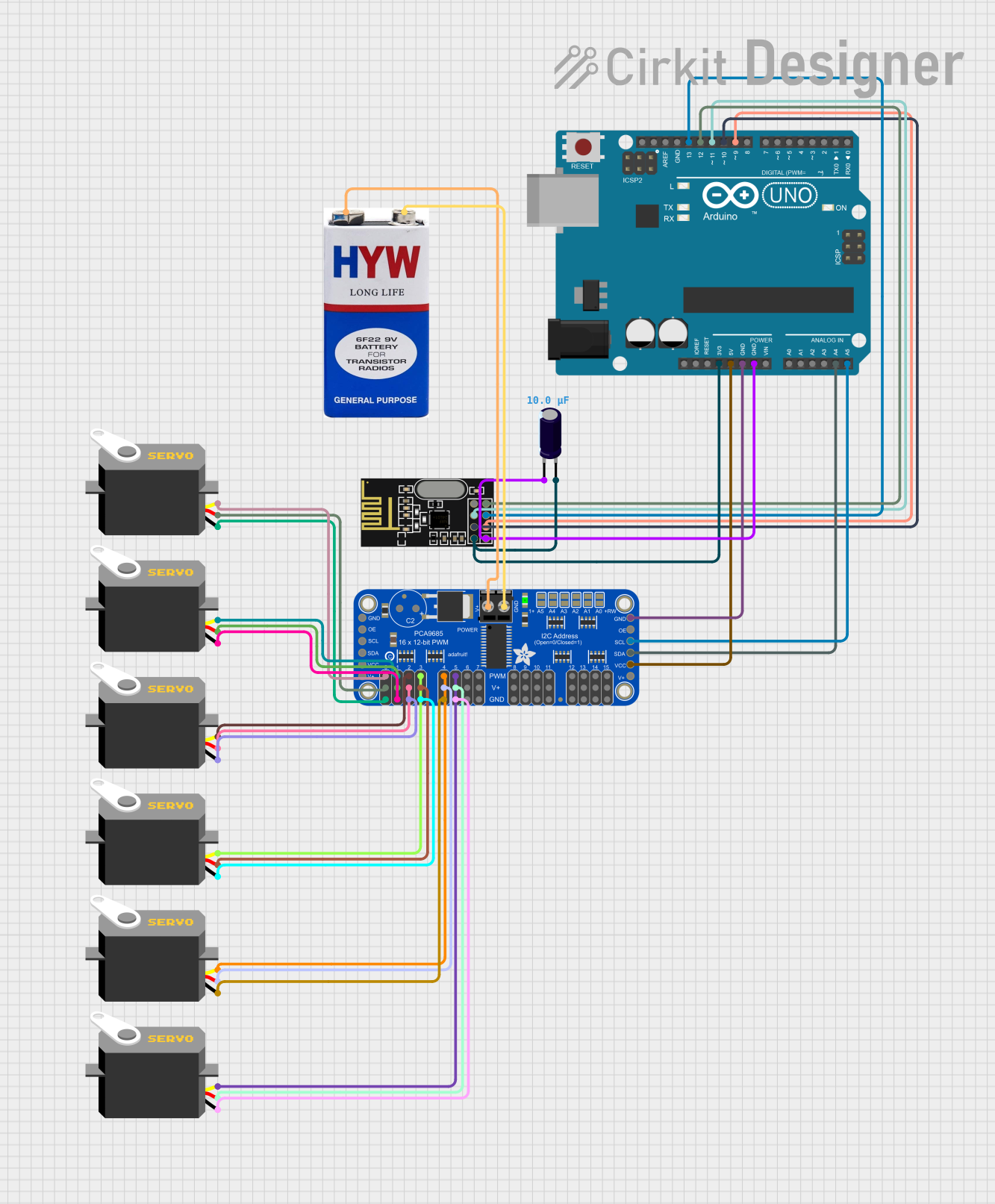
Circuit Documentation
Summary of the Circuit
This circuit is designed to control multiple servo motors using an Arduino UNO as the main microcontroller, interfaced with an Adafruit PCA9685 PWM Servo Breakout board to drive the servos. Communication with external devices is facilitated by an NRF24L01 transceiver module. The circuit is powered by a 9V battery, and an electrolytic capacitor is used for voltage smoothing.
Component List
Arduino UNO
- Microcontroller board based on the ATmega328P
- It has 14 digital input/output pins, 6 analog inputs, a 16 MHz quartz crystal, a USB connection, a power jack, an ICSP header, and a reset button.
Servo Motors
- Actuators that can be precisely controlled for angular or linear position, velocity, and acceleration.
- Each servo has three connections: ground (gnd), power (vcc), and control signal (pulse).
NRF24L01
- A 2.4GHz transceiver module with an embedded baseband protocol engine.
- It has connections for power (VCC, GND), SPI interface (MOSI, MISO, SCK, CSN), and a Chip Enable (CE) pin.
Adafruit PCA9685 PWM Servo Breakout
- A 16-channel, 12-bit PWM Fm+ I2C-bus LED controller.
- It has connections for power (VCC, GND, PWRIN), I2C interface (SDA, SCL), and PWM outputs for each channel.
9V Battery
- Provides power to the circuit.
Electrolytic Capacitor
- Used for voltage smoothing and filtering.
- It has a capacitance of 0.00001 Farads.
Wiring Details
Arduino UNO
3.3Vconnected to NRF24L01 VCC (3V) and Electrolytic Capacitor (+)5Vconnected to Adafruit PCA9685 PWM Servo Breakout VCCGNDconnected to Adafruit PCA9685 PWM Servo Breakout GND, NRF24L01 GND, and Electrolytic Capacitor (-)A4 (SDA)connected to Adafruit PCA9685 PWM Servo Breakout SDAA5 (SCL)connected to Adafruit PCA9685 PWM Servo Breakout SCLD9connected to NRF24L01 CED10connected to NRF24L01 CSND11 (MOSI)connected to NRF24L01 MOSID12 (MISO)connected to NRF24L01 MISOD13 (SCK)connected to NRF24L01 SCK
Servo Motors
gndconnected to Adafruit PCA9685 PWM Servo Breakout GNDvccconnected to Adafruit PCA9685 PWM Servo Breakout 5.0Vpulseconnected to respective PWM channels on Adafruit PCA9685 PWM Servo Breakout (PWM0, PWM1, PWM2, PWM3, PWM4, PWM5)
NRF24L01
VCC (3V)connected to Arduino UNO 3.3V and Electrolytic Capacitor (+)GNDconnected to Arduino UNO GND and Electrolytic Capacitor (-)CEconnected to Arduino UNO D9CSNconnected to Arduino UNO D10SCKconnected to Arduino UNO D13MISOconnected to Arduino UNO D12MOSIconnected to Arduino UNO D11
Adafruit PCA9685 PWM Servo Breakout
VCCconnected to Arduino UNO 5VGNDconnected to Arduino UNO GND and all Servo Motors gndPWRINconnected to 9V battery (+)PWM0 - PWM5connected to respective Servo Motors pulseSDAconnected to Arduino UNO A4SCLconnected to Arduino UNO A5
9V Battery
+connected to Adafruit PCA9685 PWM Servo Breakout PWRIN-connected to Adafruit PCA9685 PWM Servo Breakout GND
Electrolytic Capacitor
+connected to Arduino UNO 3.3V and NRF24L01 VCC (3V)-connected to Arduino UNO GND and NRF24L01 GND
Documented Code
#include <Wire.h>
#include <Adafruit_PWMServoDriver.h>
#include <SPI.h>
#include <nRF24L01.h>
#include <RF24.h>

// nRF24L01 Setup: CE and CSN pins
RF24 radio(9, 10);  // CE = Pin 9, CSN = Pin 10
const byte address[6] = "00001";  // Must match transmitter address

// Create PCA9685 PWM driver object
Adafruit_PWMServoDriver pwm = Adafruit_PWMServoDriver();

int potValues[6];  // Array to store the received potentiometer values

// Servo motor pulse range (150 - 600 is typical for many servos)
int servoMin = 150;
int servoMax = 600;

void setup()
{
  Serial.begin(9600);

  // Initialize the nRF24L01
  radio.begin();
  radio.openReadingPipe(0, address);  // Set the receiver address
  radio.setPALevel(RF24_PA_MIN);
  radio.startListening();  // Set as receiver

  // Initialize the PCA9685
  pwm.begin();
  pwm.setPWMFreq(50);  // Set PWM frequency to 50Hz (for servos)
}

void loop()
{
  // Check if data is available
  if (radio.available())
  {
    // Receive the potentiometer values
    radio.read(&potValues, sizeof(potValues));

    // Use the potentiometer values to control the servos
    for (int i = 0; i < 6; i++)
    {
      int pulseWidth = map(potValues[i], 0, 1023, servoMin, servoMax);  // Map to servo pulse width
      pwm.setPWM(i, 0, pulseWidth);  // Set PWM for the ith servo
    }
  }
}
This code is responsible for initializing the NRF24L01 module and the PCA9685 PWM driver, receiving potentiometer values wirelessly, and controlling the servo motors by mapping the received values to the appropriate pulse widths.