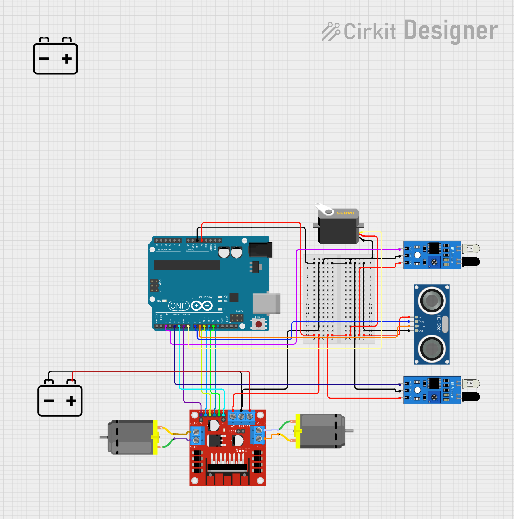
Arduino-Controlled Robotic Vehicle with Ultrasonic and IR Sensors

Circuit Documentation
Summary
The circuit in question is designed to control a pair of DC motors using an L298N motor driver module, interfaced with an Arduino UNO microcontroller. The circuit also includes a pair of IR sensors and an HC-SR04 ultrasonic sensor for distance measurement or obstacle detection. A servo motor is also part of the system, which can be used for steering or other actuation purposes. The entire circuit is powered by 12V batteries, with voltage regulation provided for the 5V components.
Component List
Microcontroller
- Arduino UNO: A microcontroller board based on the ATmega328P. It has a variety of digital and analog I/O pins and is used for controlling the various components in the circuit.
Sensors
- HC-SR04 Ultrasonic Sensor: A sensor used for measuring distances via ultrasonic waves.
- IR Sensor: An infrared sensor used for detecting proximity or measuring the intensity of IR light.
Actuators
- DC Motor: An electric motor that converts electrical energy into mechanical energy.
- Servo: A rotary actuator that allows for precise control of angular position.
Motor Driver
- L298N DC Motor Driver: A module that allows for the control of two DC motors. It can drive the motors in both directions and at varying speeds.
Power Supply
- 12V Battery: Provides the power required for the motors and the motor driver module.
Wiring Details
Arduino UNO
- 5V: Connected to the VCC of the HC-SR04 Ultrasonic Sensor, both IR sensors, the Servo, and the 5V input of the L298N motor driver.
- GND: Common ground for the HC-SR04 Ultrasonic Sensor, both IR sensors, the Servo, and the L298N motor driver.
- D8: Connected to the TRIG pin of the HC-SR04 Ultrasonic Sensor.
- D9: Connected to the ECHO pin of the HC-SR04 Ultrasonic Sensor.
- D4: Connected to the output of one IR sensor.
- D2: Connected to the output of the other IR sensor.
- D7: Connected to the pulse pin of the Servo.
- D5 (ENA): Controls the speed of one set of DC motor terminals.
- D6 (ENB): Controls the speed of the other set of DC motor terminals.
- D12 (IN1): Controls one input of the L298N motor driver.
- D13 (IN2): Controls another input of the L298N motor driver.
- D10 (IN3): Controls the third input of the L298N motor driver.
- D11 (IN4): Controls the fourth input of the L298N motor driver.
HC-SR04 Ultrasonic Sensor
- VCC: Connected to the 5V output of the Arduino UNO.
- GND: Connected to the common ground.
- TRIG: Connected to pin D8 of the Arduino UNO.
- ECHO: Connected to pin D9 of the Arduino UNO.
IR Sensors
- VCC: Connected to the 5V output of the Arduino UNO.
- GND: Connected to the common ground.
- OUT: One sensor's output is connected to pin D4 and the other to pin D2 of the Arduino UNO.
DC Motors
- Motor Terminals: Each motor is connected to two output terminals of the L298N motor driver.
L298N DC Motor Driver
- 5V: Connected to the 5V output of the Arduino UNO.
- GND: Connected to the common ground.
- 12V: Connected to the positive terminal of the 12V battery.
- IN1, IN2, IN3, IN4: Controlled by pins D12, D13, D10, and D11 of the Arduino UNO respectively.
- ENA, ENB: Controlled by pins D5 and D6 of the Arduino UNO respectively.
- OUT1, OUT2, OUT3, OUT4: Connected to the terminals of the DC motors.
Servo
- VCC: Connected to the 5V output of the Arduino UNO.
- GND: Connected to the common ground.
- Pulse: Connected to pin D7 of the Arduino UNO.
12V Battery
- +: Connected to the 12V input of the L298N motor driver.
- -: Connected to the common ground.
Documented Code
// Define motor driver pins
const int motorPin1 = 12; // IN1
const int motorPin2 = 13; // IN2
const int motorPin3 = 10; // IN3
const int motorPin4 = 11; // IN4
const int ENA = 5;
const int ENB = 6;

void setup() {
  // Initialize pins
  pinMode(motorPin1, OUTPUT);
  pinMode(motorPin2, OUTPUT);
  pinMode(motorPin3, OUTPUT);
  pinMode(motorPin4, OUTPUT);
  pinMode(ENA, OUTPUT);
  pinMode(ENB, OUTPUT);

  // Initialize Serial Monitor
  Serial.begin(9600);
}

void loop() {
  // Beginning test
  Serial.println("Beginning test");

  // Move forward at half speed
  moveForward(128);
  delay(2000);

  // Move backward at full speed
  moveBackward(255);
  delay(2000);

  // Stop rover
  stopMotor();
  delay(1000);
}

// Function to move rover forward
void moveForward(int speed) { // Speed between 0 - 255
  analogWrite(ENA, speed);
  analogWrite(ENB, speed);
  digitalWrite(motorPin1, HIGH);
  digitalWrite(motorPin2, LOW);
  digitalWrite(motorPin3, HIGH);
  digitalWrite(motorPin4, LOW);
  Serial.println("Motor moving forward");
}

// Function to move rover backward
void moveBackward(int speed) { // Speed between 0 - 255
  analogWrite(ENA, speed);
  analogWrite(ENB, speed);
  digitalWrite(motorPin1, LOW);
  digitalWrite(motorPin2, HIGH);
  digitalWrite(motorPin3, LOW);
  digitalWrite(motorPin4, HIGH);
  Serial.println("Motor moving backward");
}

// Function to stop rover
void stopMotor() {
  digitalWrite(ENA, LOW);
  digitalWrite(ENB, LOW);
  Serial.println("Motor stopped");
}
This code is designed to control the motors connected to the L298N motor driver using the Arduino UNO. It includes functions to move the motors forward and backward at specified speeds, as well as to stop the motors. The Serial Monitor is used for debugging purposes, printing out the status of the motors during operation.