
Arduino UNO WiFi-Controlled Stepper Motor Driver with Battery Backup
View and Edit Project In Cirkit Designer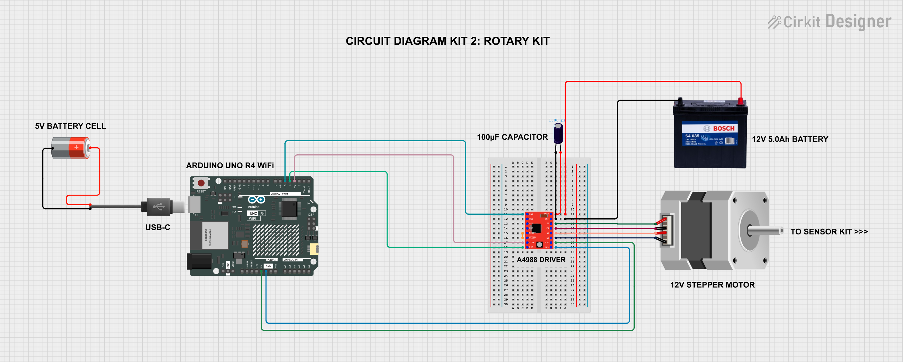
Circuit Documentation
Summary
This document provides a detailed overview of a circuit that includes an Arduino UNO R4 WiFi, a stepper motor, a stepper motor driver, capacitors, batteries, and a USB Type-C connector. The circuit is designed to control the stepper motor using the Arduino, with power supplied by a 12V battery and a 5V battery.
Component List
Arduino UNO R4 WiFi
- Description: A microcontroller board based on the ATmega328P, featuring WiFi capabilities.
- Pins: OFF, GND, VRTC, IIC0_SCL, IIC0_SDA, 3V3, GPIO 41, GPIO 0, GPIO 42, GPIO 43, GPIO 44, BOOT, IOREF, RESET, 5V, VIN, A0, A1, A2, A3, A4, A5, RSPCKA, CIPO, COPI, D0/RX, D1/TX, D2, D3, D4, D5, D6, D7, D8, D9, D10, D11, D12, D13, AREF, SDA, SCL
Stepper Motor (Bipolar)
- Description: A bipolar stepper motor with four pins.
- Pins: D, B, C, A
Electrolytic Capacitor
- Description: A capacitor used for filtering and smoothing voltage.
- Pins: -, +
- Properties:
- Capacitance: 0.000001 Farads
12V 200Ah Battery
- Description: A high-capacity battery providing 12V.
- Pins: GND, 12V
5V Battery
- Description: A battery providing 5V.
- Pins: +, -
USB Type-C
- Description: A USB Type-C connector.
- Pins: +, -
A4988 Stepper Motor Driver (Red)
- Description: A driver module for controlling a stepper motor.
- Pins: ENABLE, MS1, MS2, MS3, RESET, SLEEP, STEP, DIR, VMOT, GND, 2B, 2A, 1A, 1B, VDD
Wiring Details
Arduino UNO R4 WiFi
- D5 is connected to ENABLE of the A4988 Stepper Motor Driver.
- D3 is connected to STEP of the A4988 Stepper Motor Driver.
- D4 is connected to DIR of the A4988 Stepper Motor Driver.
- 5V is connected to VDD of the A4988 Stepper Motor Driver.
- GND is connected to GND of the A4988 Stepper Motor Driver.
Stepper Motor (Bipolar)
- A is connected to 2B of the A4988 Stepper Motor Driver.
- C is connected to 2A of the A4988 Stepper Motor Driver.
- B is connected to 1A of the A4988 Stepper Motor Driver.
- D is connected to 1B of the A4988 Stepper Motor Driver.
Electrolytic Capacitor
- + is connected to VMOT of the A4988 Stepper Motor Driver and 12V of the 12V 200Ah Battery.
- - is connected to GND of the A4988 Stepper Motor Driver and GND of the 12V 200Ah Battery.
12V 200Ah Battery
- 12V is connected to + of the Electrolytic Capacitor.
- GND is connected to - of the Electrolytic Capacitor.
5V Battery
- + is connected to + of the USB Type-C.
- - is connected to - of the USB Type-C.
USB Type-C
- + is connected to + of the 5V Battery.
- - is connected to - of the 5V Battery.
A4988 Stepper Motor Driver (Red)
- ENABLE is connected to D5 of the Arduino UNO R4 WiFi.
- VMOT is connected to + of the Electrolytic Capacitor.
- GND is connected to - of the Electrolytic Capacitor and GND of the Arduino UNO R4 WiFi.
- 2B is connected to A of the Stepper Motor.
- 2A is connected to C of the Stepper Motor.
- RESET is connected to SLEEP of the A4988 Stepper Motor Driver.
- 1A is connected to B of the Stepper Motor.
- 1B is connected to D of the Stepper Motor.
- STEP is connected to D3 of the Arduino UNO R4 WiFi.
- VDD is connected to 5V of the Arduino UNO R4 WiFi.
- DIR is connected to D4 of the Arduino UNO R4 WiFi.
Documented Code
Arduino UNO R4 WiFi Code
File Name: sketch.ino
void setup() {
  // put your setup code here, to run once:

}

void loop() {
  // put your main code here, to run repeatedly:

}
File Name: documentation.txt
This document provides a comprehensive overview of the circuit, including the components used, their connections, and the code for the Arduino UNO R4 WiFi.