
Arduino UNO R4 WiFi-Based Fire and Gas Detection System with SMS Alerts
View and Edit Project In Cirkit Designer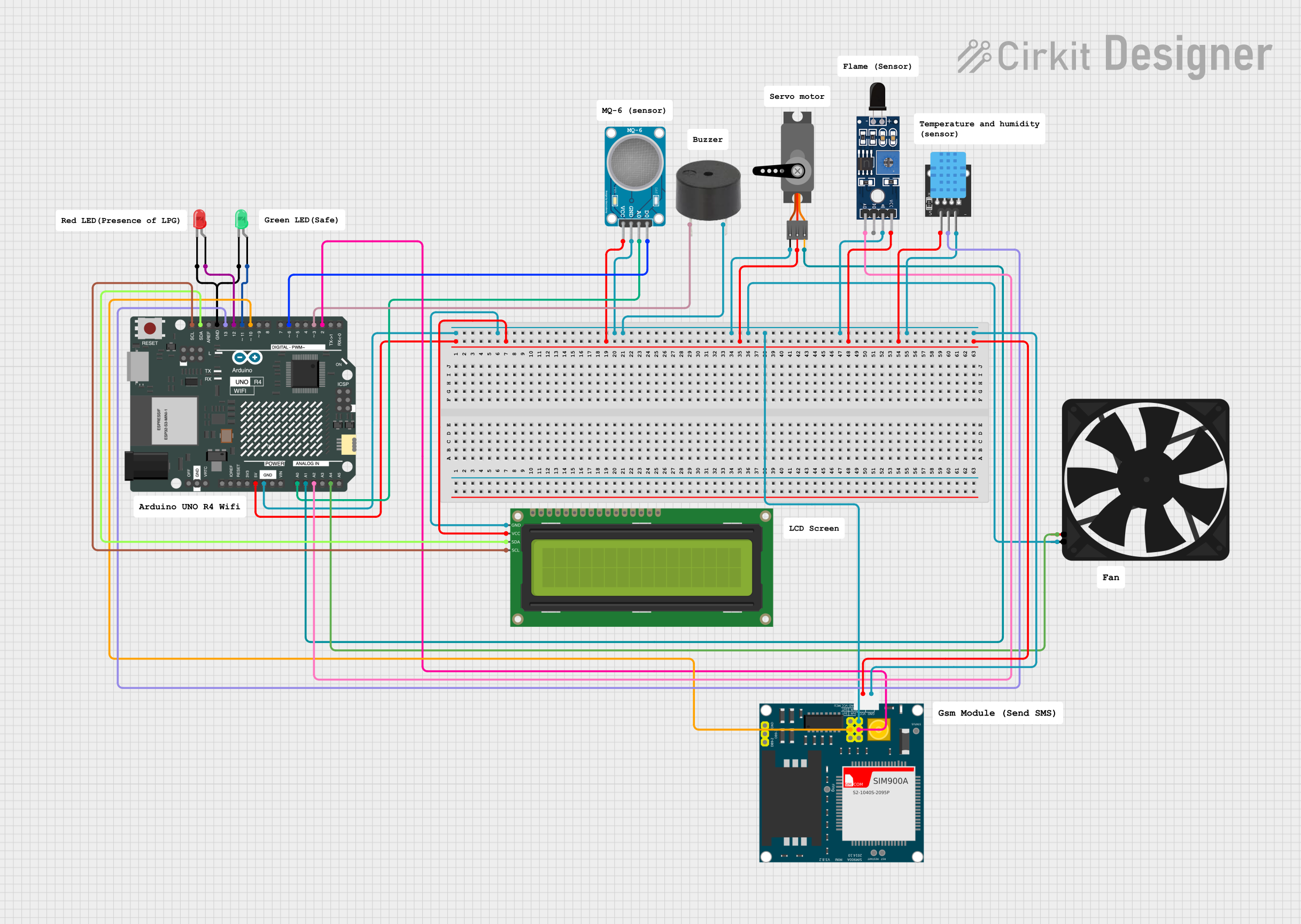
Circuit Documentation
Summary
This circuit is designed to monitor environmental conditions using various sensors and respond to specific events. It reads values from a DHT11 sensor, Flame sensor, and MQ-6 gas sensor. The temperature and humidity are displayed on an LCD screen. The circuit checks for fire presence and detects LPG gas. If fire is detected, it displays "Fire detected" on the LCD and sends an SMS. If LPG gas is detected, it displays "LPG Gas Detected", turns on a red LED, rotates a servo motor to 180 degrees, activates a buzzer, turns on a fan, and sends an SMS. If no gas is detected, it displays "LPG Not Detected" and the gas value on the LCD, and turns on a green LED.
Component List
Arduino UNO R4 WiFi
- Description: Microcontroller board
- Pins: OFF, GND, VRTC, IIC0_SCL, IIC0_SDA, 3V3, GPIO 41, GPIO 0, GPIO 42, GPIO 43, GPIO 44, BOOT, IOREF, RESET, 5V, VIN, A0, A1, A2, A3, A4, A5, RSPCKA, CIPO, COPI, D0/RX, D1/TX, D2, D3, D4, D5, D6, D7, D8, D9, D10, D11, D12, D13, AREF, SDA, SCL
LED: Two Pin (red)
- Description: Red LED
- Pins: cathode, anode
LED: Two Pin (green)
- Description: Green LED
- Pins: cathode, anode
Buzzer
- Description: Buzzer
- Pins: PIN, GND
Servo
- Description: Servo motor
- Pins: GND, VCC, PWM
MQ-6 SENSOR LPG GAS
- Description: LPG gas sensor
- Pins: VCC, GND, A0, D0
Fan
- Description: Fan
- Pins: GND, 5V
SIM900A
- Description: GSM module
- Pins: GND, DB9-3 (RXD), DB9-2 (TXD), 5V, 3VR, 5VR, 3VT, 5VT, VCC, Ring, RESTART, RESET, STATUS
Sensor SHT113 Flame
- Description: Flame sensor
- Pins: A0, D0, GND, VCC
KY-015 DHT11
- Description: Temperature and humidity sensor
- Pins: 5V, S, GND
16x2 I2C LCD
- Description: LCD display
- Pins: GND, VCC, SDA, SCL
Wiring Details
Arduino UNO R4 WiFi
- 5V: Connected to VCC of 16x2 I2C LCD, MQ-6 SENSOR LPG GAS, Servo, Sensor SHT113 Flame, KY-015 DHT11, SIM900A
- GND: Connected to GND of 16x2 I2C LCD, MQ-6 SENSOR LPG GAS, Buzzer, Servo, Fan, SIM900A, Sensor SHT113 Flame, KY-015 DHT11
- D12: Connected to anode of LED: Two Pin (red)
- D11: Connected to anode of LED: Two Pin (green)
- D3: Connected to PIN of Buzzer
- A1: Connected to PWM of Servo
- A0: Connected to A0 of MQ-6 SENSOR LPG GAS
- A2: Connected to A0 of Sensor SHT113 Flame
- A4: Connected to 5V of Fan
- D2: Connected to 5VR of SIM900A
- D6: Connected to D0 of MQ-6 SENSOR LPG GAS
- D10: Connected to 5VT of SIM900A
- D13: Connected to S of KY-015 DHT11
- SDA: Connected to SDA of 16x2 I2C LCD
- SCL: Connected to SCL of 16x2 I2C LCD
LED: Two Pin (red)
- cathode: Connected to GND of Arduino UNO R4 WiFi
- anode: Connected to D12 of Arduino UNO R4 WiFi
LED: Two Pin (green)
- cathode: Connected to GND of Arduino UNO R4 WiFi
- anode: Connected to D11 of Arduino UNO R4 WiFi
Buzzer
- PIN: Connected to D3 of Arduino UNO R4 WiFi
- GND: Connected to GND of Arduino UNO R4 WiFi
Servo
- GND: Connected to GND of Arduino UNO R4 WiFi
- VCC: Connected to 5V of Arduino UNO R4 WiFi
- PWM: Connected to A1 of Arduino UNO R4 WiFi
MQ-6 SENSOR LPG GAS
- VCC: Connected to 5V of Arduino UNO R4 WiFi
- GND: Connected to GND of Arduino UNO R4 WiFi
- A0: Connected to A0 of Arduino UNO R4 WiFi
- D0: Connected to D6 of Arduino UNO R4 WiFi
Fan
- GND: Connected to GND of Arduino UNO R4 WiFi
- 5V: Connected to A4 of Arduino UNO R4 WiFi
SIM900A
- GND: Connected to GND of Arduino UNO R4 WiFi
- 5V: Connected to 5V of Arduino UNO R4 WiFi
- 5VR: Connected to D2 of Arduino UNO R4 WiFi
- 5VT: Connected to D10 of Arduino UNO R4 WiFi
Sensor SHT113 Flame
- A0: Connected to A2 of Arduino UNO R4 WiFi
- GND: Connected to GND of Arduino UNO R4 WiFi
- VCC: Connected to 5V of Arduino UNO R4 WiFi
KY-015 DHT11
- 5V: Connected to 5V of Arduino UNO R4 WiFi
- S: Connected to D13 of Arduino UNO R4 WiFi
- GND: Connected to GND of Arduino UNO R4 WiFi
16x2 I2C LCD
- GND: Connected to GND of Arduino UNO R4 WiFi
- VCC: Connected to 5V of Arduino UNO R4 WiFi
- SDA: Connected to SDA of Arduino UNO R4 WiFi
- SCL: Connected to SCL of Arduino UNO R4 WiFi
Code Documentation
/*
 * This Arduino sketch reads values from a DHT11 sensor, Flame sensor, and
 * MQ-6 gas sensor. It displays temperature and humidity on an LCD screen,
 * checks for fire presence, and detects LPG gas. If fire is detected, it
 * displays 'Fire detected' on the LCD and sends an SMS. If LPG gas is
 * detected, it displays 'LPG Gas Detected', turns on a red LED, rotates a
 * servo motor to 180 degrees, activates a buzzer, turns on a fan, and sends
 * an SMS. If no gas is detected, it displays 'LPG Not Detected' and the gas
 * value on the LCD, and turns on a green LED.
 */

#include <Servo.h>
#include <Wire.h>
#include <LiquidCrystal_I2C.h>
#include <SoftwareSerial.h>
#include <DHT.h>

// Pin definitions
const int redLedPin = 12;
const int greenLedPin = 11;
const int buzzerPin = 3;
const int fanPin = A4;
const int mq6Pin = A0;
const int servoPin = A1;
const int gsmRxPin = 2;
const int gsmTxPin = 10;
const int flamePin = A2;
const int dhtPin = 13;

// LCD address and dimensions
LiquidCrystal_I2C lcd(0x27, 16, 2);

// Servo object
Servo myServo;

// GSM module
SoftwareSerial gsm(gsmRxPin, gsmTxPin);

// DHT sensor
#define DHTTYPE DHT11
DHT dht(dhtPin, DHTTYPE);

void setup() {
  // Initialize serial communication
  Serial.begin(9600);
  gsm.begin(9600);

  // Initialize pins
  pinMode(redLedPin, OUTPUT);
  pinMode(greenLedPin, OUTPUT);
  pinMode(buzzerPin, OUTPUT);
  pinMode(fanPin, OUTPUT);
  pinMode(mq6Pin, INPUT);
  pinMode(flamePin, INPUT);

  // Initialize servo
  myServo.attach(servoPin);

  // Initialize LCD
  lcd.init();
  lcd.backlight();
  lcd.print("System Ready");
  delay(2000);
  lcd.clear();

  // Initialize DHT sensor
  dht.begin();
}

void loop() {
  // Read DHT11