
Arduino UNO Controlled Motor System with Temperature Sensing and LCD Feedback
View and Edit Project In Cirkit Designer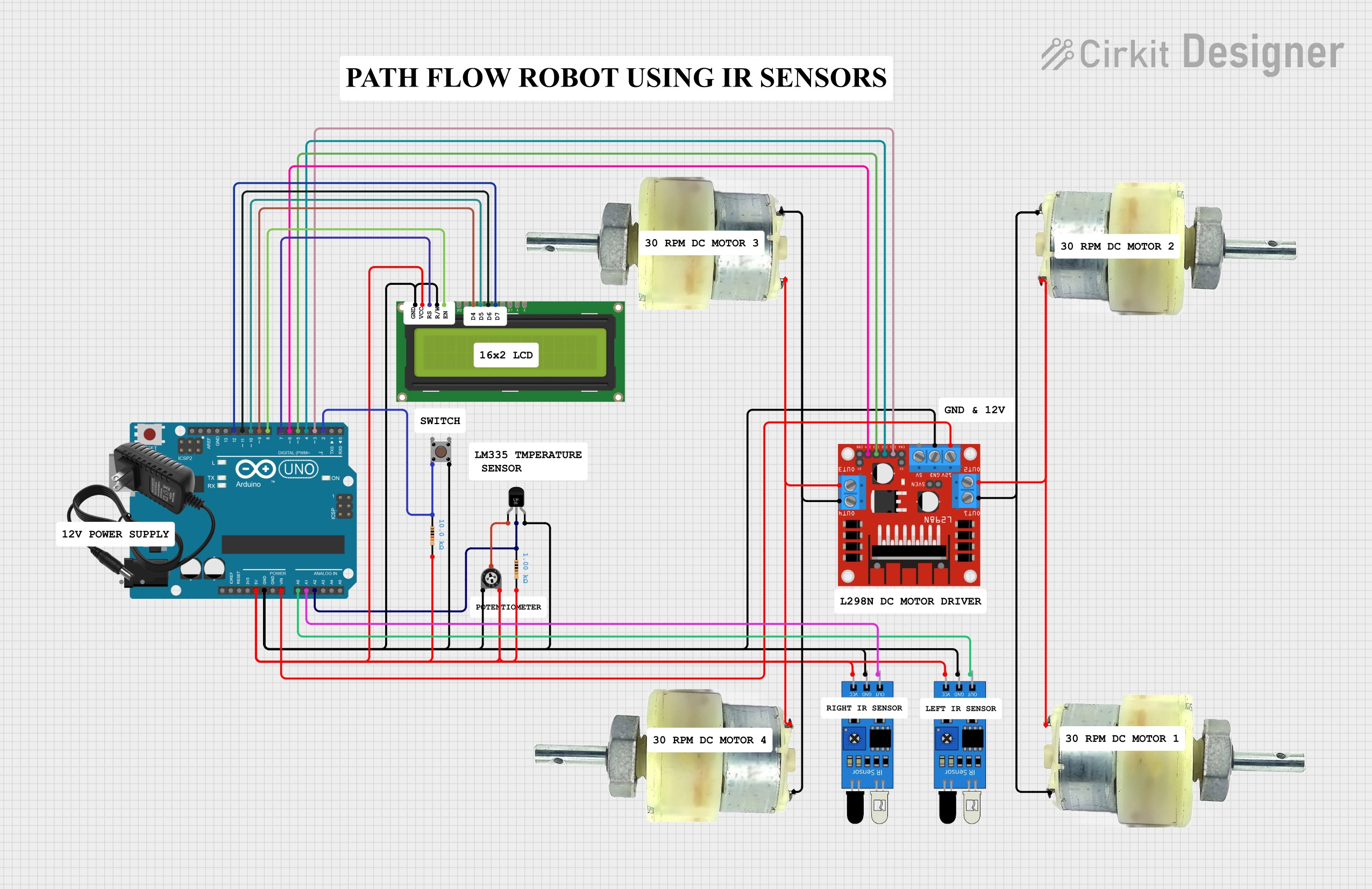
Circuit Documentation
Summary
This circuit is designed to control and monitor a system that includes DC motors, temperature sensing, and user input through a pushbutton. An Arduino UNO microcontroller serves as the central processing unit, interfacing with an L298N DC motor driver to control two 12V geared motors. The temperature is monitored by an LM35 temperature sensor, and the user can interact with the system via a pushbutton. An LCD display provides a user interface for feedback. The circuit also includes IR sensors for additional input or sensing capabilities.
Component List
L298N DC Motor Driver
- Description: A module used for controlling up to two DC motors.
- Pins: OUT1, OUT2, 12V, GND, 5V, OUT3, OUT4, ENA, IN1, IN2, IN3, IN4, ENB
Temperature Sensor (LM35)
- Description: A precision temperature sensor with an analog output.
- Pins: +Vs, Vout, GND
Resistor (10k Ohms)
- Description: A resistor with a resistance of 10k Ohms.
- Pins: pin1, pin2
Trimmer Potentiometer (10k Ohms)
- Description: An adjustable potentiometer used for setting a variable resistance.
- Pins: leg1, wiper, leg2
Pushbutton
- Description: A simple pushbutton switch for user input.
- Pins: Pin 3 (out), Pin 4 (out), Pin 1 (in), Pin 2 (in)
12V Geared Motor
- Description: A motor with a gear reduction for increased torque.
- Pins: Terminal 1, Terminal 2
Arduino UNO
- Description: A microcontroller board based on the ATmega328P.
- Pins: IOREF, Reset, 3.3V, 5V, GND, Vin, A0-A5, SCL, SDA, AREF, D0-D13
LCD Display 16x2
- Description: A 16x2 character LCD display for user interface.
- Pins: LEDK, LEDA, DB0-DB7, E, RW, RS, VO, VDD, VSS
Resistor (1k Ohms)
- Description: A resistor with a resistance of 1k Ohms.
- Pins: pin1, pin2
12V Power Supply
- Description: A power supply unit providing 12V.
- Pins: +, -
IR Sensor
- Description: An infrared sensor for detecting proximity or receiving IR signals.
- Pins: out, gnd, vcc
Wiring Details
L298N DC Motor Driver
- 12V: Connected to 12V power supply
- GND: Connected to system ground
- OUT1, OUT2: Connected to one 12V geared motor
- OUT3, OUT4: Connected to another 12V geared motor
- IN1-IN4: Controlled by Arduino UNO digital pins D3-D6
- ENA, ENB: Possibly connected to PWM outputs for speed control (not specified)
Temperature Sensor (LM35)
- +Vs: Connected to the wiper of the trimmer potentiometer
- Vout: Connected to Arduino UNO analog pin A2 through a 1k Ohm resistor
- GND: Connected to system ground
Resistor (10k Ohms)
- One end connected to the 5V supply
- The other end connected to the pushbutton and Arduino UNO digital pin D2
Trimmer Potentiometer (10k Ohms)
- One end connected to 5V supply
- The other end connected to system ground
- Wiper connected to LM35 +Vs
Pushbutton
- One side connected to 10k Ohm resistor and Arduino UNO digital pin D2
- The other side connected to system ground
12V Geared Motor
- Terminals connected to the L298N DC motor driver outputs
Arduino UNO
- 5V: Connected to 5V supply rail
- GND: Connected to system ground
- Vin: Connected to 12V supply (possibly through L298N)
- A0, A1: Connected to IR sensors
- A2: Connected to LM35 temperature sensor through a 1k Ohm resistor
- D2-D6: Connected to L298N DC motor driver and pushbutton
- D7-D12: Connected to LCD display
LCD Display 16x2
- VDD: Connected to 5V supply rail
- VSS, RW: Connected to system ground
- RS: Connected to Arduino UNO digital pin D8
- VO: Connected to Arduino UNO digital pin D7 (contrast control)
- DB4-DB7: Connected to Arduino UNO digital pins D9-D12
IR Sensor
- vcc: Connected to 5V supply rail
- gnd: Connected to system ground
- out: Connected to Arduino UNO analog pins A0 and A1
Documented Code
Arduino UNO Code (sketch.ino)
void setup() {
  // put your setup code here, to run once:

}

void loop() {
  // put your main code here, to run repeatedly:

}
Note: The provided code is a template and does not include specific functionality. It needs to be completed with the logic for controlling the motors, reading the temperature sensor, reading the IR sensors, debouncing the pushbutton, and updating the LCD display.