
Wi-Fi Enabled Water Quality Monitoring System with ESP8266 and Arduino 101
View and Edit Project In Cirkit Designer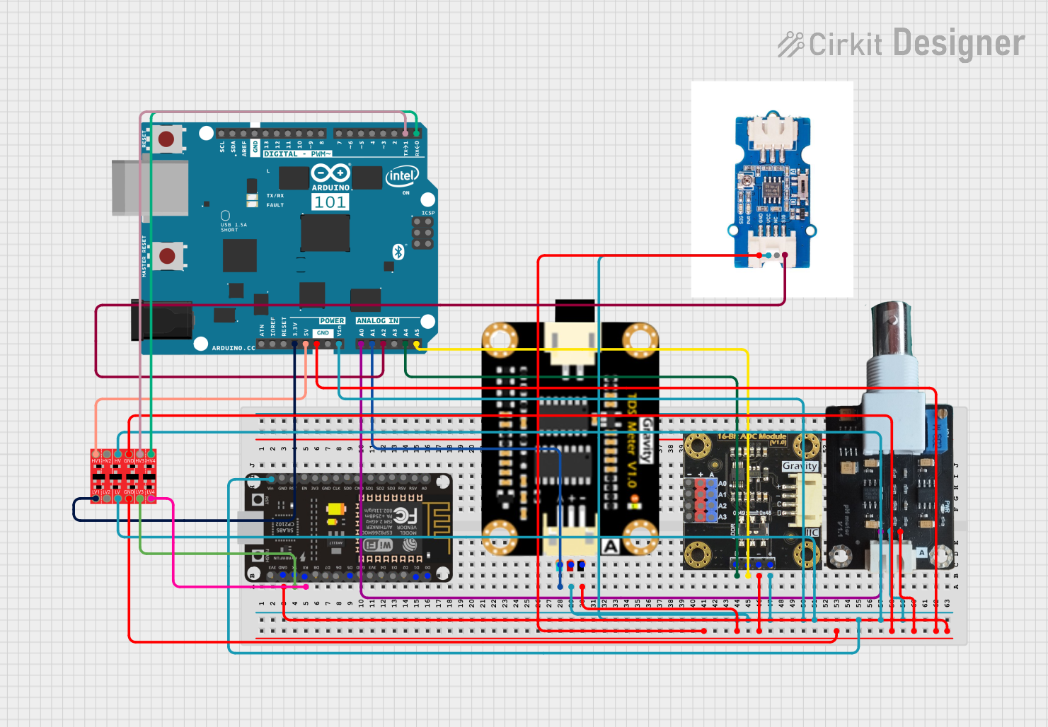
Circuit Documentation
Summary
This document provides a detailed overview of a circuit that includes an ESP8266 NodeMCU, an Arduino 101, various sensors, and a Bi-Directional Logic Level Converter. The circuit is designed to interface multiple sensors with the microcontrollers, enabling data acquisition and processing.
Component List
ESP8266 NodeMCU
- Description: A low-cost Wi-Fi microcontroller with GPIO, ADC, and UART interfaces.
- Pins: D0, D1, D2, D3, D4, 3V3, GND, D5, D6, D7, D8, RX, TX, A0, RSV, SD3, SD2, SD1, CMD, SD0, CLK, EN, RST, VIN
pH Meter V1.1
- Description: A sensor module for measuring the pH level of a solution.
- Pins: DATA, VCC, GND
Bi-Directional Logic Level Converter
- Description: A module for converting voltage levels between different logic families.
- Pins: HV1, HV2, HV, GND, HV3, HV4, LV1, LV2, LV, LV3, LV4
TDS Sensor Module
- Description: A sensor module for measuring the Total Dissolved Solids (TDS) in water.
- Pins: TDS Negative, TDS Positive, TDS A
Gravity: I2C ADS1115 16-Bit ADC Module
- Description: An analog-to-digital converter module with I2C interface.
- Pins: VCC, GND, SCL, SDA, A0_VCC, A1_VCC, A2_VCC, A3_VCC, A0_A, A1_A, A2_A, A3_A
Arduino 101
- Description: A microcontroller board based on the Intel Curie module.
- Pins: A5/SCL, A4/SDA, AREF, GND, D13/SCK, D12/MISO, D11 PWM/MOSI, D10 PWM/SS, D9 PWM, D8, D7, D6 PWM, D5 PWM, D4, D3 PWM, D2, D1/TX, D0/RX, AIN, ioref, RESET, 3V3, 5V, VIN, A0, A1, A2, A3, ICSP MISO, ICSP SCK, ICSP MOSI
Turbidity Sensor
- Description: A sensor module for measuring the turbidity (cloudiness) of water.
- Pins: GND, VCC, NC, SIG
Wiring Details
ESP8266 NodeMCU
GND is connected to:
- TDS Sensor Module (TDS Negative)
- Turbidity Sensor (GND)
- Gravity: I2C ADS1115 16-Bit ADC Module (GND)
- Bi-Directional Logic Level Converter (GND)
- pH Meter V1.1 (GND)
- Arduino 101 (GND)
TX is connected to:
- Bi-Directional Logic Level Converter (LV3)
RX is connected to:
- Bi-Directional Logic Level Converter (LV4)
VIN is connected to:
- TDS Sensor Module (TDS Positive)
- Turbidity Sensor (VCC)
- Gravity: I2C ADS1115 16-Bit ADC Module (VCC)
- Arduino 101 (VIN)
- Bi-Directional Logic Level Converter (LV)
- Bi-Directional Logic Level Converter (HV)
- pH Meter V1.1 (VCC)
pH Meter V1.1
DATA is connected to:
- Arduino 101 (A0)
VCC is connected to:
- ESP8266 NodeMCU (VIN)
GND is connected to:
- ESP8266 NodeMCU (GND)
Bi-Directional Logic Level Converter
LV3 is connected to:
- ESP8266 NodeMCU (TX)
LV4 is connected to:
- ESP8266 NodeMCU (RX)
HV1 is connected to:
- Arduino 101 (5V)
HV3 is connected to:
- Arduino 101 (D1/TX)
HV4 is connected to:
- Arduino 101 (D0/RX)
LV1 is connected to:
- Arduino 101 (3V3)
GND is connected to:
- ESP8266 NodeMCU (GND)
LV is connected to:
- ESP8266 NodeMCU (VIN)
HV is connected to:
- ESP8266 NodeMCU (VIN)
TDS Sensor Module
TDS Negative is connected to:
- ESP8266 NodeMCU (GND)
TDS Positive is connected to:
- ESP8266 NodeMCU (VIN)
TDS A is connected to:
- Arduino 101 (A1)
Gravity: I2C ADS1115 16-Bit ADC Module
VCC is connected to:
- ESP8266 NodeMCU (VIN)
GND is connected to:
- ESP8266 NodeMCU (GND)
SDA is connected to:
- Arduino 101 (A4/SDA)
SCL is connected to:
- Arduino 101 (A5/SCL)
Arduino 101
A0 is connected to:
- pH Meter V1.1 (DATA)
A1 is connected to:
- TDS Sensor Module (TDS A)
A2 is connected to:
- Turbidity Sensor (SIG)
A4/SDA is connected to:
- Gravity: I2C ADS1115 16-Bit ADC Module (SDA)
A5/SCL is connected to:
- Gravity: I2C ADS1115 16-Bit ADC Module (SCL)
D0/RX is connected to:
- Bi-Directional Logic Level Converter (HV4)
D1/TX is connected to:
- Bi-Directional Logic Level Converter (HV3)
3V3 is connected to:
- Bi-Directional Logic Level Converter (LV1)
5V is connected to:
- Bi-Directional Logic Level Converter (HV1)
VIN is connected to:
- ESP8266 NodeMCU (VIN)
GND is connected to:
- ESP8266 NodeMCU (GND)
Turbidity Sensor
GND is connected to:
- ESP8266 NodeMCU (GND)
VCC is connected to:
- ESP8266 NodeMCU (VIN)
SIG is connected to:
- Arduino 101 (A2)
Code
No code is provided for this circuit.
This document provides a comprehensive overview of the circuit, including the components used, their connections, and the wiring details. This should serve as a useful reference for understanding and replicating the circuit.