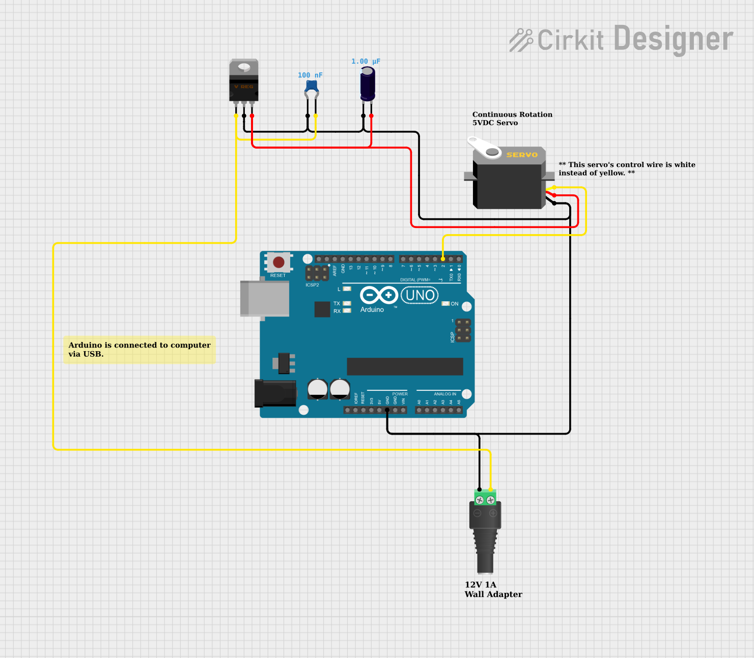
Arduino-Controlled Servo Motor with Variable Voltage Regulation

Circuit Documentation
Summary of the Circuit
This circuit is designed to control a servo motor using an Arduino UNO microcontroller. The servo is powered by a voltage regulated supply, which is connected to a 2.1mm Barrel Jack with Terminal Block. The voltage regulator ensures that the servo receives a stable voltage, while the capacitors are used to filter the power supply to prevent any voltage spikes or noise. The servo is controlled by the Arduino UNO through one of its digital pins, which sends pulse-width modulation (PWM) signals to the servo to control its position.
Component List
Servo
- Description: A motor capable of precise control of angular position.
- Pins: Ground (gnd), Power (vcc), Control Signal (pulse).
Ceramic Capacitor
- Description: A capacitor used for filtering and stabilizing the voltage supply.
- Capacitance: 0.1 µF (microfarads).
Electrolytic Capacitor
- Description: A polarized capacitor with higher capacitance than ceramic capacitors, used for power supply filtering.
- Capacitance: 1 µF (microfarads).
Voltage Regulator - Variable
- Description: A device that maintains a constant output voltage regardless of changes in load current or input voltage.
- Pins: Adjustment (ADJ), Output (OUT), Input (IN).
2.1mm Barrel Jack with Terminal Block
- Description: A connector for power supply input, typically used with wall adapters.
- Pins: Positive (POS), Negative (NEG).
Arduino UNO
- Description: A microcontroller board based on the ATmega328P, used for controlling various electronic components.
- Pins: Multiple digital and analog pins, power pins (3.3V, 5V, GND, Vin), communication pins (SCL, SDA), and others.
Wiring Details
Servo
- Ground: Connected to the ground net, which includes the GND pin of the Arduino UNO, the negative pin of the electrolytic capacitor, the negative terminal of the barrel jack, and the OUT pin of the voltage regulator.
- Power (vcc): Connected to the positive net, which includes the IN pin of the voltage regulator and the positive pin of the electrolytic capacitor.
- Control Signal (pulse): Connected to the digital pin D2 of the Arduino UNO.
Ceramic Capacitor
- Pin0: Connected to the ground net.
- Pin1: Connected to the ADJ pin of the voltage regulator and the positive terminal of the barrel jack.
Electrolytic Capacitor
- Negative (-): Connected to the ground net.
- Positive (+): Connected to the positive net.
Voltage Regulator - Variable
- Adjustment (ADJ): Connected to the positive terminal of the barrel jack and pin1 of the ceramic capacitor.
- Output (OUT): Connected to the ground net.
- Input (IN): Connected to the positive net.
2.1mm Barrel Jack with Terminal Block
- Positive (POS): Connected to the ADJ pin of the voltage regulator and pin1 of the ceramic capacitor.
- Negative (NEG): Connected to the ground net.
Documented Code
The following code is written for the Arduino UNO microcontroller to control the servo motor:
/**
 * This example demonstrates how to control a continuous rotation servo motor.
 * In this example, the servo spins forward for 1 second, pauses for 1 second,
 * spins backwards for 1 second, and pauses for 1 second in a loop.
 *
 * This example was written by Cirkit Design LLC.
 */

#include <Servo.h>

Servo myservo;

int pos = 0;

void setup() {
  // The servo control wire is connected to Arduino D2 pin.
  myservo.attach(2);
  // Servo is stationary.
  myservo.write(90);
}

void loop() {
  // Servo spins forward at full speed for 1 second.
  myservo.write(180);
  delay(1000);
  // Servo is stationary for 1 second.
  myservo.write(90);
  delay(1000);
  // Servo spins in reverse at full speed for 1 second.
  myservo.write(0);
  delay(1000);
  // Servo is stationary for 1 second.
  myservo.write(90);
  delay(1000);
}
This code is saved in a file named sketch.ino. The code sets up the servo on digital pin 2 and controls its movement in a loop, alternating between spinning forward, pausing, spinning in reverse, and pausing.