Cirkit Designer
Your all-in-one circuit design IDE
Home /
Project Documentation
Arduino-Based GSM and GPS Water Level Monitoring System
Circuit Documentation
Summary
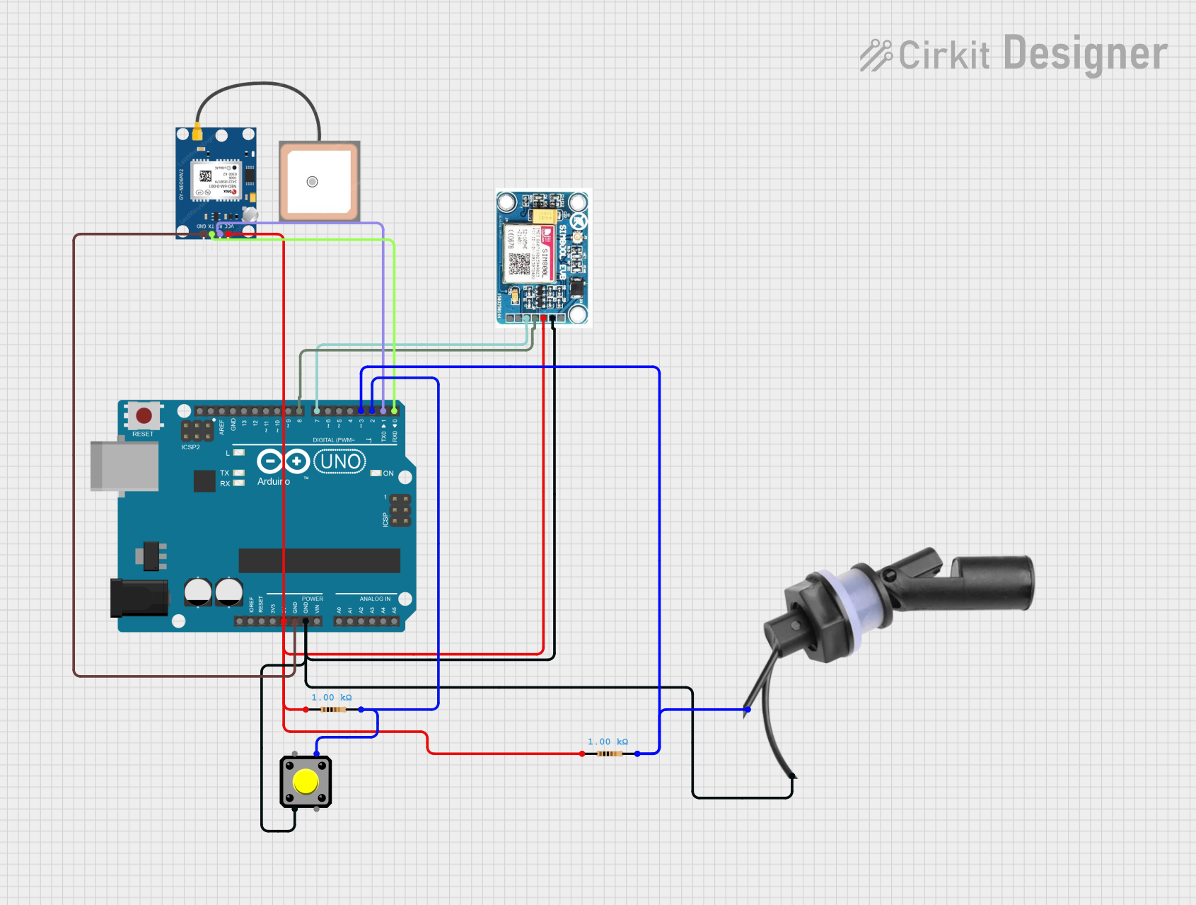
This circuit integrates an Arduino UNO microcontroller with a SIM 800L GSM module, a GPS NEO 6M module, a pushbutton, and a water level float switch sensor. The circuit is designed to interface with these components to perform various tasks, such as sending and receiving data via GSM, obtaining GPS coordinates, and detecting water levels.
Component List
Arduino UNO
- Description: A microcontroller board based on the ATmega328P.
- Pins: UNUSED, IOREF, Reset, 3.3V, 5V, GND, Vin, A0, A1, A2, A3, A4, A5, SCL, SDA, AREF, D13, D12, D11, D10, D9, D8, D7, D6, D5, D4, D3, D2, D1, D0
SIM 800L V2.0 GSM
- Description: A GSM module for sending and receiving SMS, making and receiving calls, and connecting to the internet.
- Pins: SIM_TXD, VDD, SIM.RXD, 5V/4V, GND, RST
GPS NEO 6M
- Description: A GPS module for obtaining geographic coordinates.
- Pins: VCC, RX, TX, GND
Pushbutton
- Description: A simple pushbutton switch.
- Pins: Pin 2, Pin 1, Pin 3, Pin 4
Water Level Float Switch Sensor
- Description: A sensor for detecting water levels.
- Pins: Wire2, Wire1
Resistor (1k Ohms)
- Description: A resistor with a resistance of 1000 Ohms.
- Pins: pin1, pin2
Resistor (1k Ohms)
- Description: A resistor with a resistance of 1000 Ohms.
- Pins: pin1, pin2
Wiring Details
Arduino UNO
- 5V: Connected to VCC of GPS NEO 6M, VDD of SIM 800L GSM, and pin1 of both resistors.
- GND: Connected to GND of GPS NEO 6M, GND of SIM 800L GSM, Wire2 of Water Level Float Switch Sensor, and Pin 2 of Pushbutton.
- D8: Connected to SIM_TXD of SIM 800L GSM.
- D7: Connected to SIM.RXD of SIM 800L GSM.
- D3: Connected to Wire1 of Water Level Float Switch Sensor and pin2 of one resistor.
- D2: Connected to Pin 4 of Pushbutton and pin2 of the other resistor.
- D1: Connected to RX of GPS NEO 6M.
- D0: Connected to TX of GPS NEO 6M.
SIM 800L V2.0 GSM
- VDD: Connected to 5V of Arduino UNO.
- GND: Connected to GND of Arduino UNO.
- SIM_TXD: Connected to D8 of Arduino UNO.
- SIM.RXD: Connected to D7 of Arduino UNO.
GPS NEO 6M
- VCC: Connected to 5V of Arduino UNO.
- GND: Connected to GND of Arduino UNO.
- RX: Connected to D1 of Arduino UNO.
- TX: Connected to D0 of Arduino UNO.
Pushbutton
- Pin 2: Connected to GND of Arduino UNO.
- Pin 4: Connected to D2 of Arduino UNO and pin2 of one resistor.
Water Level Float Switch Sensor
- Wire2: Connected to GND of Arduino UNO.
- Wire1: Connected to D3 of Arduino UNO and pin2 of one resistor.
Resistor (1k Ohms)
- pin1: Connected to 5V of Arduino UNO.
- pin2: Connected to D3 of Arduino UNO and Wire1 of Water Level Float Switch Sensor.
Resistor (1k Ohms)
- pin1: Connected to 5V of Arduino UNO.
- pin2: Connected to D2 of Arduino UNO and Pin 4 of Pushbutton.
Documented Code
Arduino UNO Code (sketch.ino)
void setup() {
  // put your setup code here, to run once:

}

void loop() {
  // put your main code here, to run repeatedly:

}
Additional Documentation (documentation.txt)
This documentation provides a comprehensive overview of the circuit, including a summary, detailed component list, wiring details, and the code used in the Arduino UNO microcontroller.