
Arduino UNO Controlled Alarm Clock with Motor Activation and I2C LCD Display
View and Edit Project In Cirkit Designer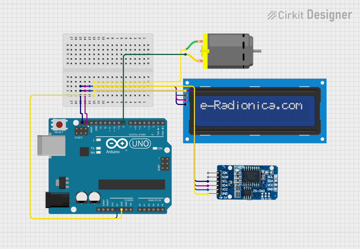
Circuit Documentation
Summary
This circuit is designed to control a DC motor based on real-time clock (RTC) alarms and display the current time and alarm status on an LCD screen. The Arduino UNO serves as the central microcontroller unit, interfacing with an RTC DS3231 module for accurate timekeeping and an I2C-enabled LCD screen for user feedback. The DC motor is controlled through one of the digital pins on the Arduino, which is toggled according to the programmed alarm times.
Component List
Arduino UNO
- Description: A microcontroller board based on the ATmega328P.
- Purpose: Acts as the central processing unit for the circuit, controlling the DC motor, interfacing with the RTC module, and driving the LCD display.
DC Motor
- Description: An electric motor that runs on direct current (DC) electricity.
- Purpose: Performs mechanical actions when activated by the Arduino according to the set alarm times.
RTC DS3231
- Description: A real-time clock module that maintains accurate timekeeping even when the main power is off.
- Purpose: Provides the current time to the Arduino, which uses it to trigger alarms and control the DC motor.
LCD screen 16x2 I2C
- Description: A 16x2 character LCD display with an I2C interface.
- Purpose: Displays the current time and alarm status for user feedback.
Wiring Details
Arduino UNO
- 5V: Powers the RTC DS3231 and the LCD screen.
- GND: Common ground for the RTC DS3231, LCD screen, and DC Motor.
- SCL: I2C clock line connected to the RTC DS3231 and LCD screen.
- SDA: I2C data line connected to the RTC DS3231 and LCD screen.
- D8: Digital output controlling the DC Motor.
DC Motor
- pin 1: Connected to the ground (GND) of the Arduino UNO.
- pin 2: Controlled by digital pin D8 of the Arduino UNO.
RTC DS3231
- VCC: Powered by the 5V output from the Arduino UNO.
- GND: Connected to the common ground of the Arduino UNO.
- SCL: Connected to the SCL pin of the Arduino UNO for I2C communication.
- SDA: Connected to the SDA pin of the Arduino UNO for I2C communication.
LCD screen 16x2 I2C
- VCC: Powered by the 5V output from the Arduino UNO.
- GND: Connected to the common ground of the Arduino UNO.
- SCL: Connected to the SCL pin of the Arduino UNO for I2C communication.
- SDA: Connected to the SDA pin of the Arduino UNO for I2C communication.
Documented Code
#include <Wire.h>
#include <RTClib.h>
#include <LiquidCrystal_I2C.h>

// Create instances
RTC_DS3231 rtc;
LiquidCrystal_I2C lcd(0x27, 16, 2); // Adjust the I2C address if necessary

// Motor control pin
const int motorPin = 8; // Pin connected to the motor

// Alarm 1 settings
const int OnHour1 = 7; // Set time to turn motor ON (24-hour format)
const int OnMin1 = 0;
const int OffHour1 = 7; // Set time to turn motor OFF
const int OffMin1 = 1;

// Alarm 2 settings
const int OnHour2 = 16; // Set time to turn motor ON (24-hour format)
const int OnMin2 = 0;
const int OffHour2 = 16; // Set time to turn motor OFF
const int OffMin2 = 1;

void setup() {
  Serial.begin(9600);
  lcd.init();
  lcd.backlight();

  pinMode(motorPin, OUTPUT); // Set motor pin as output

  if (!rtc.begin()) { // Initialize RTC and check if it's available
    Serial.println("Couldn't find RTC");
    while (1); // Stop if RTC is not available
  }

  if (rtc.lostPower()) { // Check if RTC lost power and reset time
    Serial.println("RTC lost power, setting time!");
    rtc.adjust(DateTime(F(__DATE__), F(__TIME__))); // Set RTC to compile time
  }

  lcd.clear();
  lcd.setCursor(0, 0);
  lcd.print("Alarm Clock");
  delay(1000);
  lcd.clear();
}

void loop() {
  DateTime now = rtc.now();  // Get the current time from the RTC

  // Display current time
  lcd.setCursor(0, 0);
  lcd.print("TIME: ");
  lcd.print(now.hour());
  lcd.print(":");
  if (now.minute() < 10) lcd.print("0");
  lcd.print(now.minute());
  lcd.print(":");
  if (now.second() < 10) lcd.print("0");
  lcd.print(now.second());

  // Check and trigger Alarm 1
  if (now.hour() == OnHour1 && now.minute() == OnMin1) {
    digitalWrite(motorPin, HIGH); // Turn on the motor
    lcd.setCursor(0, 1);
    lcd.print("MOTOR ON (A1) ");
  } else if (now.hour() == OffHour1 && now.minute() == OffMin1) {
    digitalWrite(motorPin, LOW); // Turn off the motor
    lcd.setCursor(0, 1);
    lcd.print("MOTOR OFF (A1)");
  }

  // Check and trigger Alarm 2
  if (now.hour() == OnHour2 && now.minute() == OnMin2) {
    digitalWrite(motorPin, HIGH); // Turn on the motor
    lcd.setCursor(0, 1);
    lcd.print("MOTOR ON (A2) ");
  } else if (now.hour() == OffHour2 && now.minute() == OffMin2) {
    digitalWrite(motorPin, LOW); // Turn off the motor
    lcd.setCursor(0, 1);
    lcd.print("MOTOR OFF (A2)");
  }

  // Display alarm times
  lcd.setCursor(0, 1);
  lcd.print("A1: ");
  lcd.print(OnHour1);
  lcd.print(":");
  if (OnMin1 < 10) lcd.print("0");
  lcd.print(OnMin1);
  lcd.print(" A2: ");
  lcd.print(OnHour2);
  lcd.print(":");
  if (OnMin2 < 10) lcd.print("0");
  lcd.print(OnMin2);

  delay(1000); // Update every second
}
This code is responsible for initializing the RTC and LCD, setting up the motor control pin, and running the main loop that checks the current time against the alarm settings to control the motor and update the display.