
ESP32-Based Battery-Powered Universal IR Remote with OLED Display
View and Edit Project In Cirkit Designer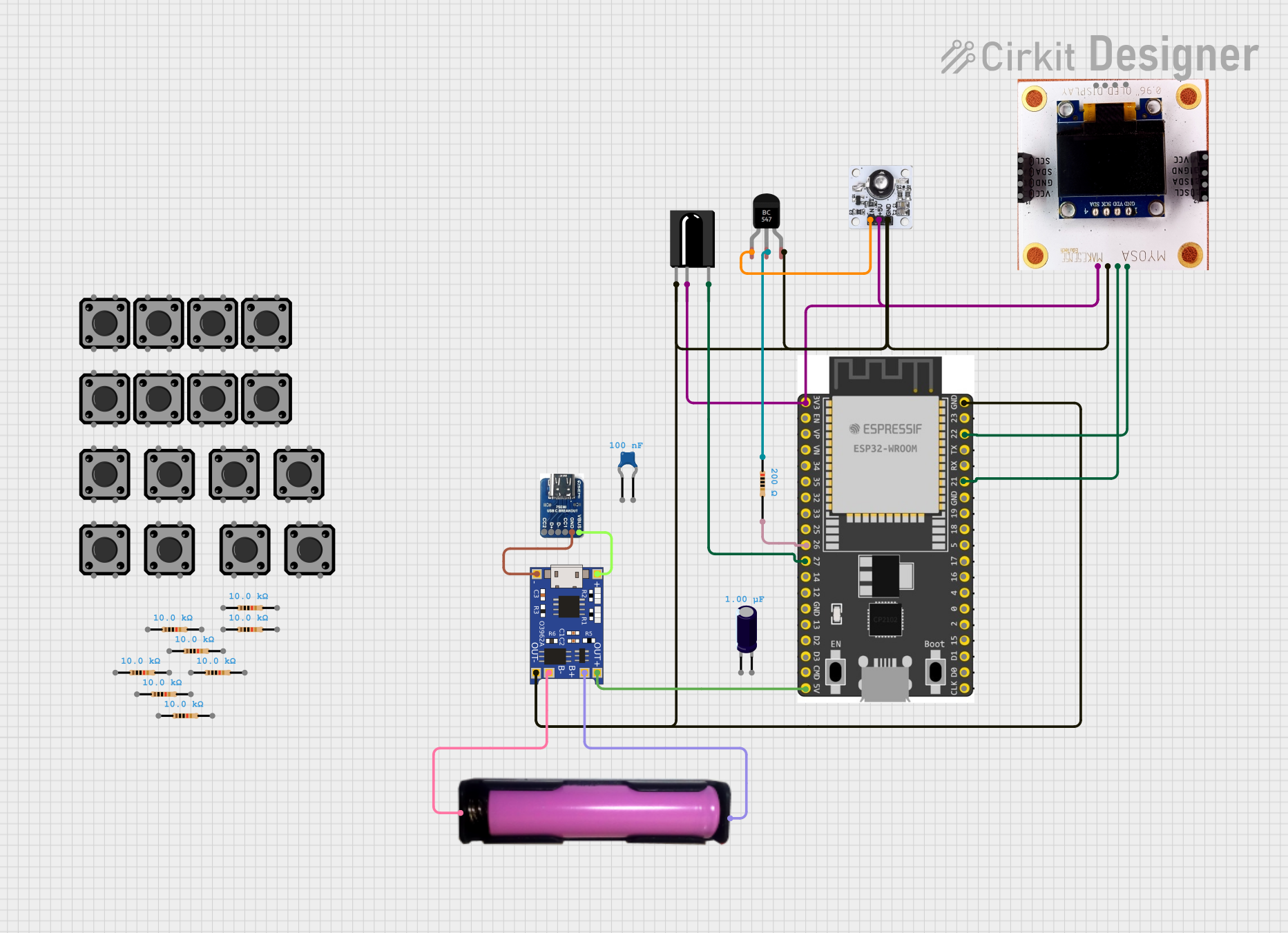
Circuit Documentation
Summary
This circuit is designed to function as an IR remote control system using an ESP32 microcontroller. The system includes an IR receiver, an IR transmitter, an OLED display for user interaction, and multiple tactile switches for input. The circuit is powered by a 18650 battery and includes a TP4056 module for battery charging. The ESP32 microcontroller is programmed to handle IR signals, display messages on the OLED, and respond to button presses.
Component List
ESP32 Wroom Dev Kit
- Description: Microcontroller with Wi-Fi and Bluetooth capabilities.
- Pins: 3V3, EN, VP, VN, GPIO 34, GPIO 35, GPIO 32, GPIO 33, GPIO 25, GPIO 26, GPIO 27, GPIO 14, GND, GPIO 13, SD2, SD3, CMD, V5, GPIO 23, GPIO 22, TXD, RXD, GPIO 21, GPIO 19, GPIO 18, GPIO 5, GPIO 17, GPIO 16, GPIO 4, GPIO 0, GPIO 2, GPIO 15, SD1, SD0, CLK
TSOP312 IR Receiver
- Description: Infrared receiver for capturing IR signals.
- Pins: GND, Vs, Data
Resistor (200 Ohms)
- Description: Resistor with a resistance of 200 Ohms.
- Pins: pin1, pin2
Ceramic Capacitor
- Description: Capacitor with a capacitance of 0.1 µF.
- Pins: pin0, pin1
18650 in holder
- Description: Battery holder for 18650 lithium-ion battery.
- Pins: GND, VCC
USB C breakout board
- Description: Breakout board for USB-C connector.
- Pins: VBUS, GND, CC1, D-, D+, CC2
940nm Infrared LED Transmitter Module
- Description: Infrared LED module for transmitting IR signals.
- Pins: IN, 5V, GND
TP4056
- Description: Lithium-ion battery charger module.
- Pins: OUT-, B-, B+, OUT+, IN-, IN+
SSD1306 I2C OLED Display
- Description: OLED display with I2C interface.
- Pins: SCL, SDA, GND, VCC
BC547 Transistor
- Description: NPN transistor.
- Pins: Collector, Base, Emitter
Electrolytic Capacitor
- Description: Capacitor with a capacitance of 1 µF.
- Pins: -, +
Resistor (10k Ohms)
- Description: Resistor with a resistance of 10k Ohms.
- Pins: pin1, pin2
Tactile Switch Buttons - 12mm Square
- Description: Tactile switch button.
- Pins: 3, 1, 4, 2
Wiring Details
ESP32 Wroom Dev Kit
- 3V3: Connected to 5V pin of 940nm Infrared LED Transmitter Module, Vs pin of TSOP312 IR Receiver, and VCC pin of SSD1306 I2C OLED Display.
- GPIO 26: Connected to pin2 of 200 Ohms Resistor.
- GPIO 27: Connected to Data pin of TSOP312 IR Receiver.
- V5: Connected to OUT+ pin of TP4056.
- GND: Connected to GND pin of 940nm Infrared LED Transmitter Module, OUT- pin of TP4056, Emitter pin of BC547 Transistor, GND pin of TSOP312 IR Receiver, and GND pin of SSD1306 I2C OLED Display.
- GPIO 22: Connected to SCL pin of SSD1306 I2C OLED Display.
- GPIO 21: Connected to SDA pin of SSD1306 I2C OLED Display.
TSOP312 IR Receiver
- GND: Connected to GND pin of ESP32 Wroom Dev Kit.
- Vs: Connected to 3V3 pin of ESP32 Wroom Dev Kit.
- Data: Connected to GPIO 27 pin of ESP32 Wroom Dev Kit.
Resistor (200 Ohms)
- pin1: Connected to Base pin of BC547 Transistor.
- pin2: Connected to GPIO 26 pin of ESP32 Wroom Dev Kit.
18650 in holder
- GND: Connected to B- pin of TP4056.
- VCC: Connected to B+ pin of TP4056.
USB C breakout board
- GND: Connected to IN- pin of TP4056.
- VBUS: Connected to IN+ pin of TP4056.
940nm Infrared LED Transmitter Module
- IN: Connected to Collector pin of BC547 Transistor.
- 5V: Connected to 3V3 pin of ESP32 Wroom Dev Kit.
- GND: Connected to GND pin of ESP32 Wroom Dev Kit.
TP4056
- OUT-: Connected to GND pin of ESP32 Wroom Dev Kit.
- B-: Connected to GND pin of 18650 in holder.
- B+: Connected to VCC pin of 18650 in holder.
- OUT+: Connected to V5 pin of ESP32 Wroom Dev Kit.
- IN-: Connected to GND pin of USB C breakout board.
- IN+: Connected to VBUS pin of USB C breakout board.
SSD1306 I2C OLED Display
- SCL: Connected to GPIO 22 pin of ESP32 Wroom Dev Kit.
- SDA: Connected to GPIO 21 pin of ESP32 Wroom Dev Kit.
- GND: Connected to GND pin of ESP32 Wroom Dev Kit.
- VCC: Connected to 3V3 pin of ESP32 Wroom Dev Kit.
BC547 Transistor
- Collector: Connected to IN pin of 940nm Infrared LED Transmitter Module.
- Base: Connected to pin1 of 200 Ohms Resistor.
- Emitter: Connected to GND pin of ESP32 Wroom Dev Kit.
Tactile Switch Buttons - 12mm Square
- Pins 3, 1, 4, 2: Connected to GPIO pins of ESP32 Wroom Dev Kit starting from GPIO 32.
Code Documentation
#include <IRremoteESP8266.h>
#include <IRrecv.h>
#include <IRsend.h>
#include <Adafruit_SSD1306.h>
#include <Adafruit_GFX.h>

// Pins
#define RECV_PIN 27
#define IR_LED_PIN 26
#define BUTTON_PIN_BASE 32 // GPIO for buttons starting from 32
#define OLED_RESET -1 // Use default for I2C OLED

// Constants
#define NUM_BUTTONS 8
#define MAX_REMOTES 5

// Globals
IRrecv irrecv(RECV_PIN);
IRsend irsend(IR_LED_PIN);
decode_results results;
Adafruit_SSD1306 display(128, 64, &Wire, OLED_RESET);

struct Remote {
  uint64_t codes[NUM_BUTTONS];
};

Remote remotes[MAX_REMOTES];
int currentRemote = 0;
int currentButton = 0;
int storedRemotes = 0;

// Functions
void setup() {
  Serial.begin(115200);

  // IR Setup
  irrecv.enableIRIn();
  irsend.begin();

  // OLED Setup
  if (!display.begin(SSD1306_I2C_ADDRESS, OLED_RESET)) {
    Serial.println(F("SSD1306 allocation failed"));
    for (;;);
  }
  display.clearDisplay();
  display.setTextSize(1);
  display.setTextColor(SSD1306_WHITE);

  // Button Setup
  for (int i = 0; i < NUM_BUTTONS; i++) {
    pinMode(BUTTON_PIN_BASE + i, INPUT_PULLUP);
  }

  // Startup Message
  displayMessage("IR Remote Ready");
}

void loop() {
  // Navigation and interaction logic
  handleButtons();

  // Check for IR input to capture or use
  if (irrecv.decode(&results)) {
    handleIRSignal();
    irrecv.resume();
  }
}

void displayMessage(String message) {
  display.clearDisplay();
  display.setCursor(0, 0);
  display.println(message);
  display.display();
}

void handleButtons() {
  for (int i = 0; i < NUM_BUTTONS; i++) {
    if (!digitalRead(BUTTON_PIN_BASE + i)) {
      delay(200); // Debounce
      if (i == 0) {
        // Add Remote Logic
        addRemote();
      } else if (i == 1) {
        // Show Remote Logic
        showRemote();
      } else if (i == 2) {
        // Delete Remote Logic
        deleteRemote();
      }
      return;
    }
  }
}

void handleIRSignal() {
  uint