Arduino UNO-Based Environmental Monitoring System with Bluetooth Connectivity
Circuit Documentation
Summary
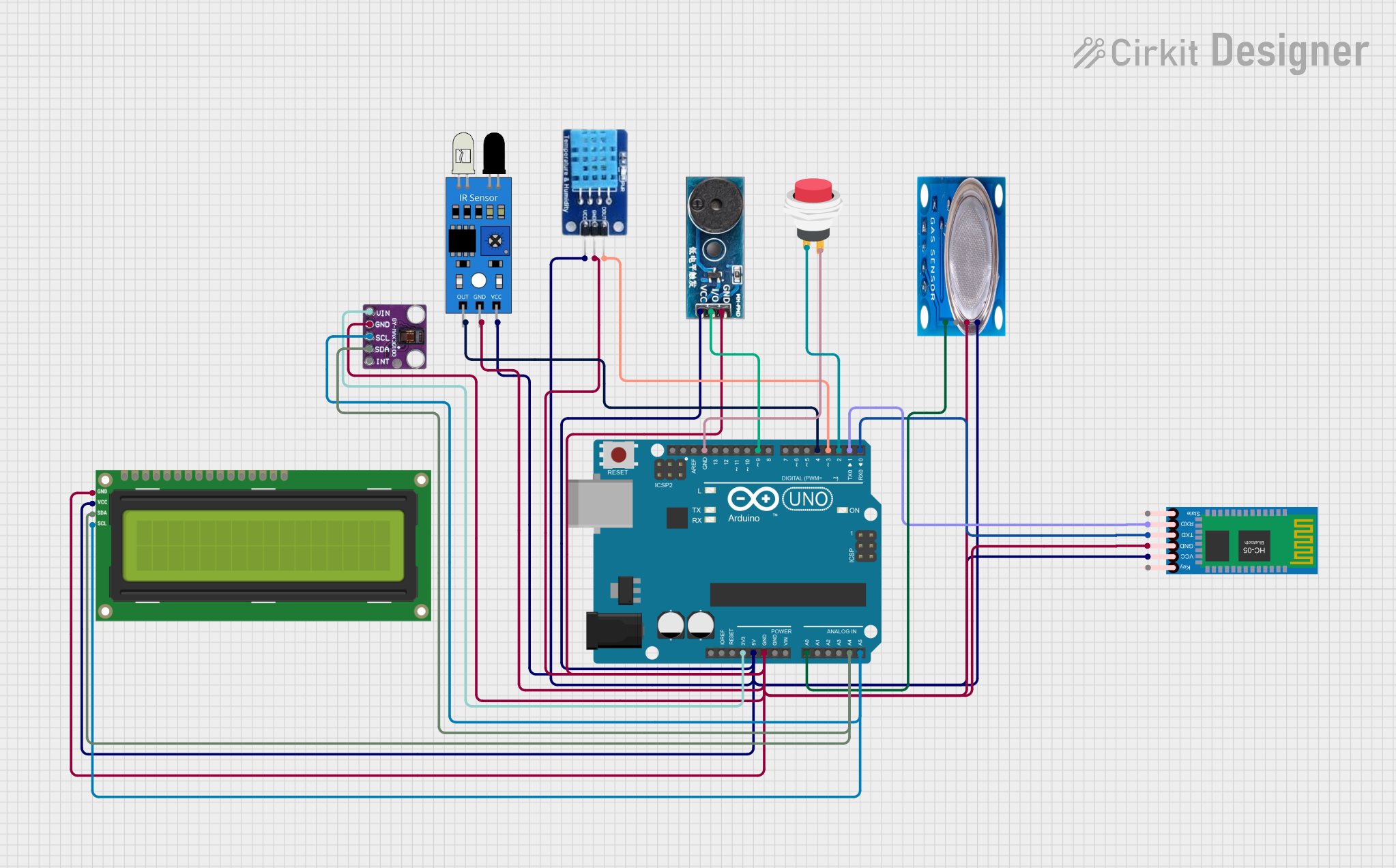
This circuit integrates various sensors and modules with an Arduino UNO microcontroller to perform multiple functions. The sensors include an MQ-5 gas sensor, an IR sensor, and a MAX30100 pulse oximeter. The circuit also features a DHT11 temperature and humidity sensor, an HC-05 Bluetooth module for wireless communication, an I2C LCD 16x2 screen for display, a buzzer module for audio alerts, and a 2-pin push switch for user input. The Arduino UNO serves as the central processing unit, interfacing with all the components to collect data, control outputs, and communicate with external devices.
Component List
MQ-5 Gas Sensor
- Pins: VCC, GND, Digi Out, Analog out
- Description: A gas sensor for detecting LPG, natural gas, and coal gas.
IR Sensor
- Pins: out, gnd, vcc
- Description: An infrared sensor for detecting proximity or motion.
MAX30100 Pulse Oximeter
- Pins: Vin, gnd, scl, sda, int
- Description: A sensor for measuring blood oxygen saturation (SpO2) and heart rate.
Arduino UNO
- Pins: UNUSED, IOREF, Reset, 3.3V, 5V, GND, Vin, A0-A5, SCL, SDA, AREF, D0-D13
- Description: A microcontroller board based on the ATmega328P.
HC-05 Bluetooth Module
- Pins: Key, VCC, TXD, RXD, State, GND
- Description: A Bluetooth module for wireless communication.
I2C LCD 16x2 Screen
- Pins: SCL, SDA, VCC (5V), GND, VDD, VO, RS, RW, E, D0-D7, BLA, BLK
- Description: A liquid crystal display for showing text and numbers.
DHT11 Temperature and Humidity Sensor
- Pins: DATA, GND, VCC
- Description: A sensor for measuring ambient temperature and humidity.
Buzzer Module
- Pins: GND, Vcc, I/O
- Description: An audio signaling device.
2Pin Push Switch
- Pins: Input +, Output +
- Description: A simple push-button switch for user input.
Wiring Details
MQ-5 Gas Sensor
- VCC: Connected to Arduino UNO 5V
- GND: Connected to Arduino UNO GND
- Analog out: Connected to Arduino UNO A0
IR Sensor
- vcc: Connected to Arduino UNO 5V
- gnd: Connected to Arduino UNO GND
- out: Connected to Arduino UNO D4
MAX30100 Pulse Oximeter
- Vin: Connected to Arduino UNO 3.3V
- gnd: Connected to Arduino UNO GND
- scl: Connected to Arduino UNO A5 (also connected to I2C LCD SCL)
- sda: Connected to Arduino UNO A4 (also connected to I2C LCD SDA)
HC-05 Bluetooth Module
- VCC: Connected to Arduino UNO 5V
- GND: Connected to Arduino UNO GND
- TXD: Connected to Arduino UNO D0
- RXD: Connected to Arduino UNO D1
I2C LCD 16x2 Screen
- SCL: Connected to Arduino UNO A5 (also connected to MAX30100 SCL)
- SDA: Connected to Arduino UNO A4 (also connected to MAX30100 SDA)
- VCC (5V): Connected to Arduino UNO 5V
- GND: Connected to Arduino UNO GND
DHT11 Temperature and Humidity Sensor
- VCC: Connected to Arduino UNO 5V
- GND: Connected to Arduino UNO GND
- DATA: Connected to Arduino UNO D3
Buzzer Module
- Vcc: Connected to Arduino UNO 5V
- GND: Connected to Arduino UNO GND
- I/O: Connected to Arduino UNO D9
2Pin Push Switch
- Input +: Connected to Arduino UNO D2
- Output +: Connected to Arduino UNO GND
Documented Code
Arduino UNO Code (sketch.ino)
void setup() {
  // put your setup code here, to run once:

}

void loop() {
  // put your main code here, to run repeatedly:

}
The provided code is a template with empty setup() and loop() functions, which are the standard structure for Arduino sketches. The setup() function is intended to contain initialization code that runs once when the microcontroller is powered on or reset. The loop() function contains the main logic of the program, which runs repeatedly as long as the microcontroller is powered.
Additional Notes
- The code for the Arduino UNO is currently a placeholder and needs to be filled in with the logic to interact with the connected sensors and modules.
- The
documentation.txtfile is empty and can be used to add further explanations, usage instructions, or any other relevant information about the circuit and its code.