
ESP32-CAM Controlled Robotics Platform with Dual DC Motors and Servomotor
View and Edit Project In Cirkit Designer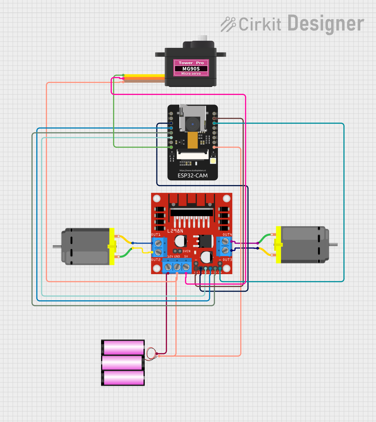
Circuit Documentation
Summary
This circuit is designed to control two DC motors and a servomotor using an ESP32-CAM microcontroller. The L298N DC motor driver is used to interface the ESP32-CAM with the motors, allowing for directional and speed control. The servomotor is directly controlled by the ESP32-CAM. A 12V battery provides power to the system, with voltage regulation for the servomotor and logic levels for the microcontroller and motor driver.
Component List
Servomotor MG90S
- Description: A small and lightweight servomotor for precise angular movement.
- Pins: SIG (Signal), VCC (Power), GND (Ground)
Battery 12V
- Description: A 12-volt battery that provides the main power source for the circuit.
- Pins: + (Positive), - (Negative)
L298N DC Motor Driver
- Description: A dual H-bridge motor driver that can drive two DC motors or one stepper motor.
- Pins: OUT1, OUT2, 12V, GND, 5V, OUT3, OUT4, 5V-ENA-JMP-I, 5V-ENA-JMP-O, +5V-J1, +5V-J2, ENA, IN1, IN2, IN3, IN4, ENB
DC Motor
- Description: A standard DC motor for rotational motion.
- Pins: pin 1, pin 2
ESP32 - CAM
- Description: A microcontroller with integrated Wi-Fi and Bluetooth capabilities, along with a camera interface.
- Pins: 5V, GND, IO12, IO13, IO15, IO14, IO2, IO4, VOT, VOR, VCC, IO0, IO16, 3V3
Wiring Details
Servomotor MG90S
- SIG: Connected to ESP32 - CAM IO4
- VCC: Connected to L298N DC motor driver 5V
- GND: Connected to the common ground net
Battery 12V
- +: Connected to L298N DC motor driver 12V
- -: Connected to the common ground net
L298N DC Motor Driver
- IN1: Connected to ESP32 - CAM IO12
- IN2: Connected to ESP32 - CAM IO14
- IN3: Connected to ESP32 - CAM IO13
- IN4: Connected to ESP32 - CAM IO15
- ENA: Connected to ESP32 - CAM IO16
- ENB: Connected to ESP32 - CAM IO0
- OUT1: Connected to DC Motor (instance 1) pin 2
- OUT2: Connected to DC Motor (instance 1) pin 1
- OUT3: Connected to DC Motor (instance 2) pin 2
- OUT4: Connected to DC Motor (instance 2) pin 1
- 12V: Connected to Battery 12V +
- 5V: Connected to Servomotor MG90S VCC
- GND: Connected to the common ground net
DC Motor (Instance 1)
- pin 1: Connected to L298N DC motor driver OUT2
- pin 2: Connected to L298N DC motor driver OUT1
DC Motor (Instance 2)
- pin 1: Connected to L298N DC motor driver OUT4
- pin 2: Connected to L298N DC motor driver OUT3
ESP32 - CAM
- IO12: Connected to L298N DC motor driver IN1
- IO13: Connected to L298N DC motor driver IN3
- IO14: Connected to L298N DC motor driver IN2
- IO15: Connected to L298N DC motor driver IN4
- IO4: Connected to Servomotor MG90S SIG
- IO0: Connected to L298N DC motor driver ENB
- IO16: Connected to L298N DC motor driver ENA
- GND: Connected to the common ground net
Documented Code
The code for the ESP32-CAM microcontroller is not provided in the input. However, the code would typically include initialization of the GPIO pins, setup of the Wi-Fi or Bluetooth communication, and the main loop to control the motors based on inputs or sensor data. The code would also handle the camera interface if it is used in the application.
// Placeholder for ESP32-CAM code
// The actual code would be here, including setup and loop functions.
Please note that the actual code for the ESP32-CAM is required to complete the documentation. The code would be placed in the respective files with the .ino and .txt extensions as indicated in the input.