
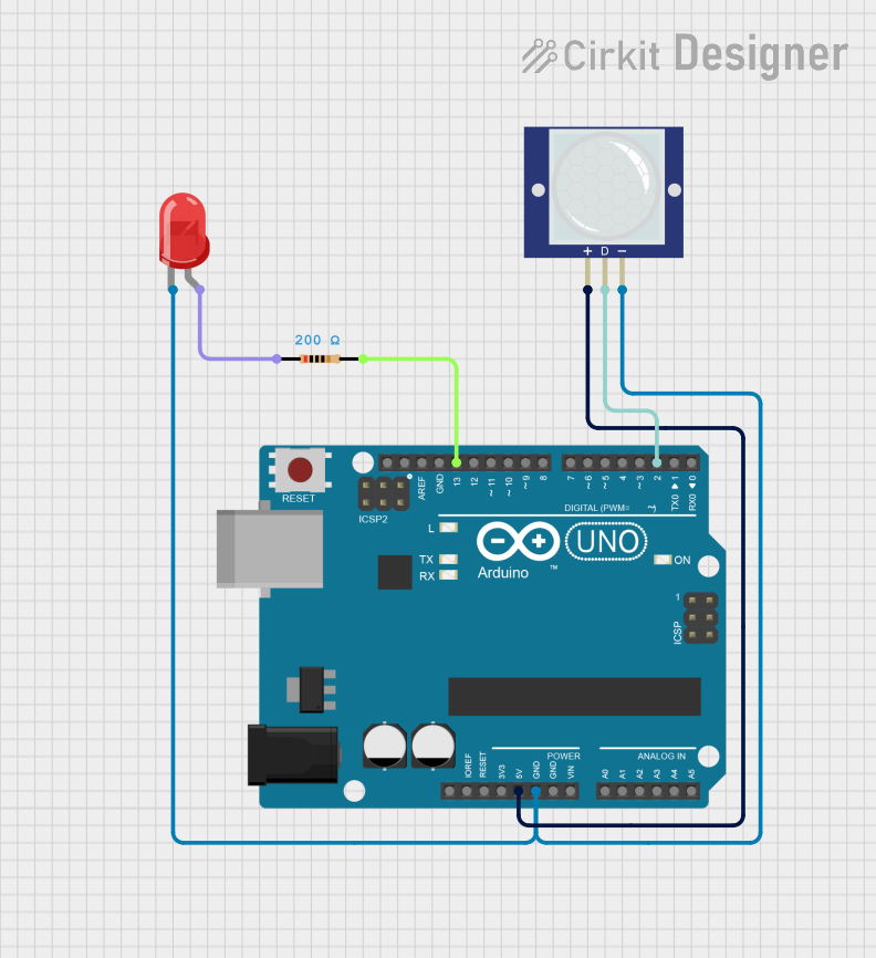
Circuit Documentation
Summary
This circuit is designed to detect motion using a PIR (Passive Infrared) motion sensor. When motion is detected, the sensor sends a signal to an Arduino UNO microcontroller, which activates a red LED to indicate the presence of motion. The circuit includes a resistor to limit the current to the LED, ensuring safe operation.
Component List
Arduino UNO
- Description: A microcontroller board based on the ATmega328P. It is used to read input from the PIR motion sensor and control the LED.
- Purpose: Acts as the central processing unit for the circuit, handling input from the sensor and output to the LED.
PIR Motion Sensor
- Description: A sensor that detects motion by measuring changes in infrared radiation.
- Purpose: Senses motion in its vicinity and sends a signal to the Arduino when motion is detected.
LED Two Pin (Red)
- Description: A red LED that lights up when motion is detected.
- Purpose: Provides a visual indication of motion detection.
Resistor
- Description: A passive electrical component that limits the current flowing through the circuit.
- Purpose: Protects the LED from excessive current, ensuring it operates safely.
Wiring Details
Arduino UNO
5V: Connected to the VCC pin of the PIR Motion Sensor.
GND: Connected to the GND pin of the PIR Motion Sensor and the Cathode pin of the LED.
D13: Connected to pin2 of the Resistor.
D2: Connected to the OUT pin of the PIR Motion Sensor.
PIR Motion Sensor
VCC: Connected to the 5V pin of the Arduino UNO.
GND: Connected to the GND pin of the Arduino UNO and the Cathode pin of the LED.
OUT: Connected to the D2 pin of the Arduino UNO.
LED Two Pin (Red)
Anode: Connected to pin1 of the Resistor.
Cathode: Connected to the GND pin of the Arduino UNO.
Resistor
pin1: Connected to the Anode pin of the LED.
pin2: Connected to the D13 pin of the Arduino UNO.
Documented Code
/*
   PIR sensor tester
*/

int ledPin = 13;                // choose the pin for the LED
int inputPin = 2;               // choose the input pin (for PIR sensor)
int pirState = LOW;             // we start, assuming no motion detected
int val = 0;                    // variable for reading the pin status

void setup() {
  pinMode(12, OUTPUT);
  digitalWrite(12, LOW);

  pinMode(ledPin, OUTPUT);      // declare LED as output
  pinMode(inputPin, INPUT);     // declare sensor as input

  Serial.begin(9600);
}

void loop() {
  val = digitalRead(inputPin);  // read input value
  if (val == HIGH) {            // check if the input is HIGH
    digitalWrite(ledPin, HIGH);  // turn LED ON
    if (pirState == LOW) {
      // we have just turned on
      Serial.println("Motion detected!");
      // We only want to print on the output change, not state
      pirState = HIGH;
    }
  } else {
    digitalWrite(ledPin, LOW); // turn LED OFF
    if (pirState == HIGH) {
      // we have just turned off
      Serial.println("Motion ended!");
      // We only want to print on the output change, not state
      pirState = LOW;
    }
  }
}
This documentation provides a comprehensive overview of the circuit, detailing each component, its purpose, and the wiring connections, along with the code that drives the functionality of the system.