
Solar-Powered Bluetooth-Controlled Robotic Car with ESP32 and Arduino
View and Edit Project In Cirkit Designer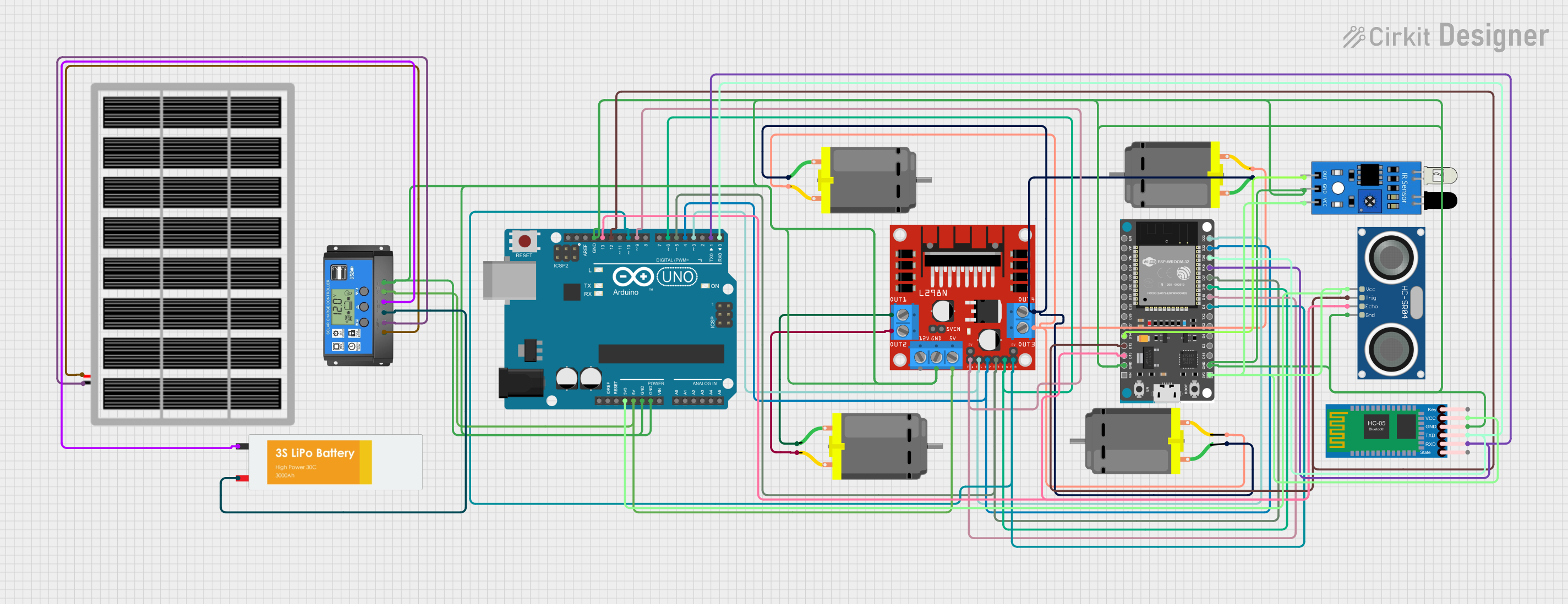
Circuit Documentation
Summary
This circuit is designed to control multiple DC motors using an L298N motor driver, interfaced with an Arduino UNO and an ESP32 Devkit V1 microcontroller. The system also includes an HC-SR04 ultrasonic sensor, an HC-05 Bluetooth module, and an IR sensor for various input and control functionalities. Power is supplied by a solar panel connected to a solar charge controller, which also charges a LiPo battery. The circuit is designed for applications such as a solar-powered remote control car with Bluetooth connectivity for control commands.
Component List
Microcontrollers
- Arduino UNO: A microcontroller board based on the ATmega328P, with digital and analog I/O pins.
- ESP32 Devkit V1: A microcontroller with Wi-Fi and Bluetooth capabilities, suitable for a wide range of applications.
Sensors and Modules
- HC-SR04 Ultrasonic Sensor: Used for distance measurement.
- HC-05 Bluetooth Module: Provides Bluetooth connectivity for wireless communication.
- IR Sensor: Detects infrared signals, which can be used for remote control or obstacle detection.
Motor Driver
- L298N DC Motor Driver: Controls the speed and direction of two DC motors.
Power Components
- Solar Panel: Converts sunlight into electrical energy.
- Solar Charge Controller: Manages the charging of the LiPo battery from the solar panel and provides power to the load.
- LiPo Battery: Stores electrical energy for use by the circuit.
Actuators
- DC Motors: Converts electrical energy into mechanical motion.
Wiring Details
Arduino UNO
- 3.3V: Powers the HC-SR04 ultrasonic sensor, HC-05 Bluetooth module, ESP32 Devkit V1, and IR sensor.
- 5V: Connected to the Load + of the Solar Charge Controller.
- GND: Common ground for the circuit.
- Digital Pins: Control signals to the L298N motor driver and communication with the HC-SR04 ultrasonic sensor and HC-05 Bluetooth module.
ESP32 Devkit V1
- 3V3 and GND: Power supply and ground connections.
- Digital Pins: Control signals to the L298N motor driver and communication with the HC-SR04 ultrasonic sensor, HC-05 Bluetooth module, and IR sensor.
HC-SR04 Ultrasonic Sensor
- VCC and GND: Power supply connections.
- TRIG and ECHO: Interface with the Arduino UNO and ESP32 Devkit V1 for distance measurement.
HC-05 Bluetooth Module
- VCC and GND: Power supply connections.
- TXD and RXD: Serial communication with the Arduino UNO and ESP32 Devkit V1.
IR Sensor
- VCC and GND: Power supply connections.
- OUT: Output signal connected to the ESP32 Devkit V1.
L298N DC Motor Driver
- 5V and GND: Power supply connections from the Arduino UNO.
- IN1, IN2, IN3, IN4: Control inputs from the Arduino UNO and ESP32 Devkit V1.
- ENA, ENB: Enable pins for motor speed control from the Arduino UNO and ESP32 Devkit V1.
- OUT1, OUT2, OUT3, OUT4: Outputs to the DC motors.
Solar Panel and Solar Charge Controller
- VCC and GND: Connections between the solar panel and the solar charge controller.
- Battery + and Battery -: Connections to the LiPo battery.
DC Motors
- Pin 1 and Pin 2: Connections to the L298N motor driver outputs.
LiPo Battery
- VCC and GND: Connections to the Solar Charge Controller for charging and power supply.
Documented Code
Arduino UNO Code
/*
 * Arduino Sketch to control L298N Motor Driver
 * using Arduino UNO.
 *
 * Connections:
 * Pin 3  -> IN1 (Motor A)
 * Pin 4  -> IN2 (Motor A)
 * Pin 5  -> IN3 (Motor B)
 * Pin 6  -> IN4 (Motor B)
 * Pin 9  -> ENA (Motor A speed control)
 * Pin 10 -> ENB (Motor B speed control)
 * GND    -> GND (of motor driver)
 */

// Pin definitions
const int IN1 = 3;
const int IN2 = 4;
const int IN3 = 5;
const int IN4 = 6;
const int ENA = 9;
const int ENB = 10;

void setup() {
  // Set all the motor control pins to outputs
  pinMode(IN1, OUTPUT);
  pinMode(IN2, OUTPUT);
  pinMode(IN3, OUTPUT);
  pinMode(IN4, OUTPUT);
  pinMode(ENA, OUTPUT);
  pinMode(ENB, OUTPUT);

  // Initialize motors to off
  digitalWrite(IN1, LOW);
  digitalWrite(IN2, LOW);
  digitalWrite(IN3, LOW);
  digitalWrite(IN4, LOW);
  analogWrite(ENA, 0);
  analogWrite(ENB, 0);
}

void loop() {
  // Example: Rotate Motor A forward at half speed
  digitalWrite(IN1, HIGH);
  digitalWrite(IN2, LOW);
  analogWrite(ENA, 128);

  // Example: Rotate Motor B backward at full speed
  digitalWrite(IN3, LOW);
  digitalWrite(IN4, HIGH);
  analogWrite(ENB, 255);

  delay(2000); // Run for 2 seconds

  // Stop motors
  digitalWrite(IN1, LOW);
  digitalWrite(IN2, LOW);
  digitalWrite(IN3, LOW);
  digitalWrite(IN4, LOW);
  analogWrite(ENA, 0);
  analogWrite(ENB, 0);

  delay(2000); // Stop for 2 seconds
}
ESP32 Devkit V1 Code
ESP32                L298N Motor Driver
------------------------------------------
GPIO 23  --------> IN1 (Motor A)
GPIO 22  --------> IN2 (Motor A)
GPIO 21  --------> IN3 (Motor B)
GPIO 19  --------> IN4 (Motor B)
GPIO 18  --------> ENA (Motor A speed control)
GPIO 5   --------> ENB (Motor B speed control)
GND      --------> GND (of motor driver)
(Note: The ESP32 code provided is a wiring guide rather than a complete sketch. A full sketch would include setup and loop functions similar to the Arduino UNO code, tailored for the ESP32's pin assignments and capabilities.)
Additional Microcontroller Code
The provided code snippets for other microcontrollers are either incomplete or not provided. For a complete documentation, the code for each microcontroller should be included with comments explaining the functionality and connections, similar to the Arduino UNO and ESP32 examples above.