
Arduino Nano Controlled Irrigation System with Humidity Sensing and LCD Display
View and Edit Project In Cirkit Designer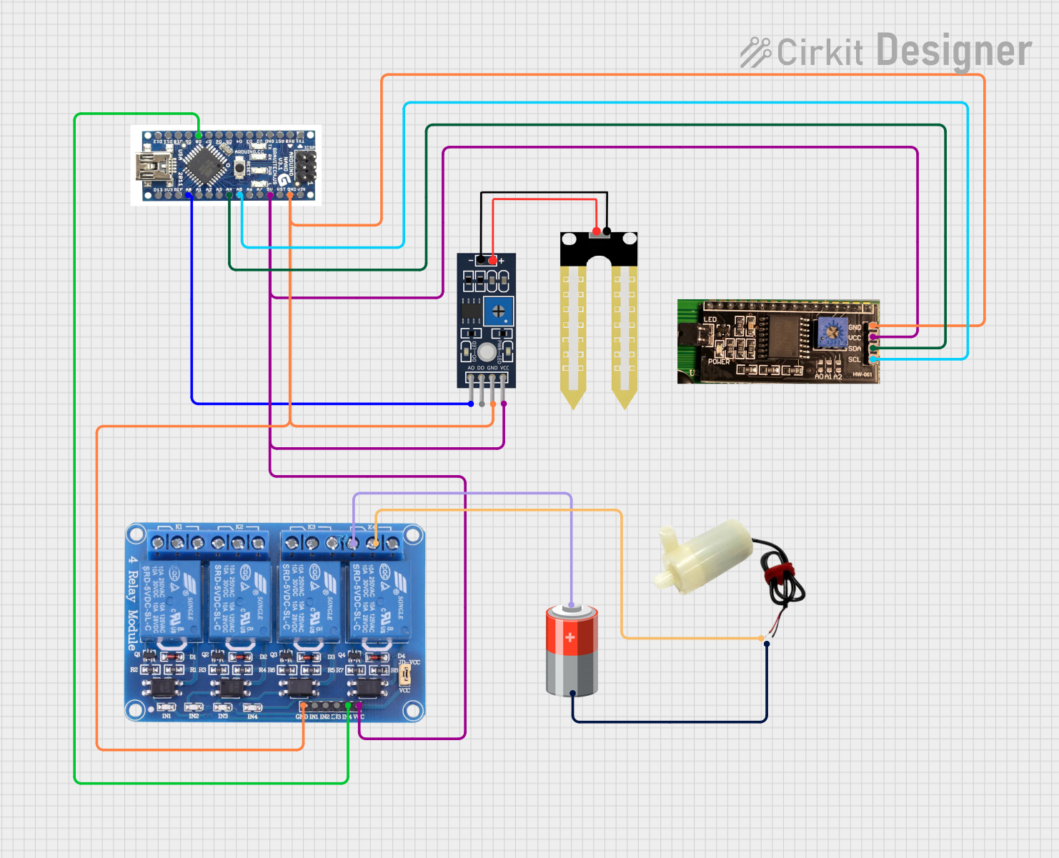
Circuit Documentation
Summary of the Circuit
This circuit is designed to interface an Arduino Nano with a 4-channel relay module, an LCD with I2C interface, a humidity sensor (YL-69), and a 5V mini water pump. The Arduino Nano serves as the central controller, reading the humidity level from the YL-69 sensor and displaying information on the LCD screen. Based on the sensor input, the Arduino can control the water pump via the relay module. The circuit is powered by a 5V battery, which supplies power to the Arduino, relay module, LCD, and humidity sensor.
Component List
Relay 4 Channel 5v
- Description: A 4-channel relay module capable of controlling up to four separate high-power devices.
- Pins: GND, IN1, IN2, IN3, IN4, VCC, COM1, COM2, COM3, COM4, NO1, NO2, NO3, NO4, NC1, NC2, NC3, NC4
LCD2004I2C
- Description: A 20x4 character LCD display with an I2C interface for easy communication with microcontrollers.
- Pins: GND, VCC, SDA, SCL
Humidity YL-69
- Description: A soil moisture sensor that provides both analog and digital outputs to indicate soil humidity levels.
- Pins: A0, D0, GND, VCC
5v mini water pump
- Description: A small water pump that operates at 5V, suitable for pumping water in small-scale projects.
- Pins: positive pin, negative pin
Arduino Nano
- Description: A compact microcontroller board based on the ATmega328, ideal for embedding into projects.
- Pins: D12, D11, D10, D9, D8, D7, D6, D5, D4, D3, D2, GND, RST, RX0, TX1, D13, 3V3, REF, A0, A1, A3, A4, A5, A6, A7, 5V, VIN
5v Battery
- Description: A power source providing a stable 5V output to power the circuit components.
- Pins: +, -
Wiring Details
Relay 4 Channel 5v
- GND: Connected to Arduino Nano GND
- IN4: Controlled by Arduino Nano D8
- VCC: Powered by Arduino Nano 5V
- COM4: Connected to the positive pin of the 5v mini water pump
- NC4: Connected to the positive terminal of the 5v Battery
LCD2004I2C
- GND: Connected to Arduino Nano GND
- VCC: Powered by Arduino Nano 5V
- SDA: Data line connected to Arduino Nano A4
- SCL: Clock line connected to Arduino Nano A5
Humidity YL-69
- A0: Analog output connected to Arduino Nano A0
- GND: Connected to Arduino Nano GND
- VCC: Powered by Arduino Nano 5V
5v mini water pump
- positive pin: Connected to Relay 4 Channel 5v COM4
- negative pin: Connected to the negative terminal of the 5v Battery
Arduino Nano
- D8: Controls Relay 4 Channel 5v IN4
- A0: Reads analog data from Humidity YL-69 A0
- A4: Connected to LCD2004I2C SDA
- A5: Connected to LCD2004I2C SCL
- 5V: Powers Relay 4 Channel 5v, LCD2004I2C, and Humidity YL-69
- GND: Common ground for Relay 4 Channel 5v, LCD2004I2C, and Humidity YL-69
5v Battery
- +: Powers Relay 4 Channel 5v NC4
- -: Connected to the negative pin of the 5v mini water pump
Documented Code
No code was provided for the microcontrollers in the circuit. The expected functionality would include reading the humidity level from the YL-69 sensor, displaying the readings on the LCD, and controlling the water pump based on the humidity level using the relay module. The code would be written for the Arduino Nano and would involve initializing the I2C interface for the LCD, setting up the digital output for the relay control, and reading the analog input from the humidity sensor.