
Arduino Mega 2560-Based Wireless Control System with OLED Display and Rotary Encoder
View and Edit Project In Cirkit Designer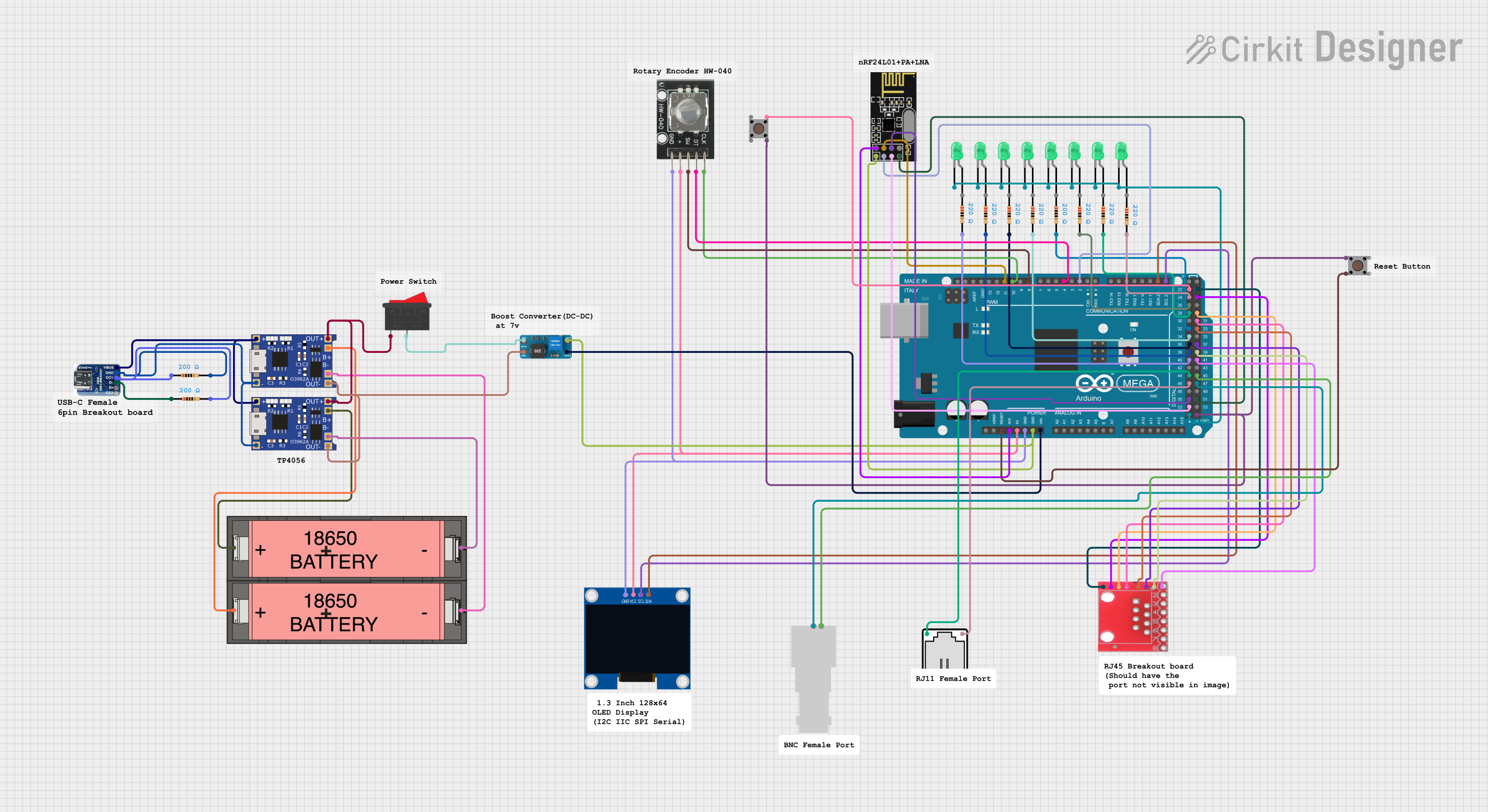
Circuit Documentation
Summary
This document provides a detailed overview of a circuit that includes an Arduino Mega 2560 microcontroller, various sensors, LEDs, and other components. The circuit is designed to interface with multiple peripherals, including a rotary encoder, an OLED display, and an NRF24L01 wireless module. The document includes a component list, wiring details, and the embedded code used in the microcontroller.
Component List
Arduino Mega 2560
- Description: A microcontroller board based on the ATmega2560.
- Pins: IOREF, RESET, 3V3, 5V, GND, VIN, A0-A15, D0-D53, AREF, SDA, SCL
HW-040 Rotary Encoder
- Description: A rotary encoder module used for detecting rotational position.
- Pins: GND, +, SW, DT, CLK
NRF24L01
- Description: A wireless transceiver module.
- Pins: IRQ (not used), MOSI, CSN, VCC (3V), GND, CE, SCK, MISO
Pushbutton
- Description: A simple pushbutton switch.
- Pins: Pin 1 (in), Pin 2 (in), Pin 3 (out), Pin 4 (out)
LED: Two Pin (green)
- Description: A green LED.
- Pins: cathode, anode
RJ45
- Description: An RJ45 connector.
- Pins: R1+, R1-, R2+, R2-, R3+, R3-, 5V, GND
Resistor
- Description: A resistor with various resistance values.
- Pins: pin1, pin2
- Properties: Resistance (200-220 Ohms)
128x64 OLED Display (I2C IIC SPI Serial)
- Description: An OLED display module.
- Pins: GND, SDA, SCL, VCC
DC to DC Boost Converter
- Description: A module to boost DC voltage.
- Pins: vin-, vin+, out+, out-
TP4056
- Description: A lithium battery charger module.
- Pins: OUT-, B-, B+, OUT+, IN-, IN+
Li-ion 18650 Battery
- Description: A rechargeable lithium-ion battery.
- Pins: -, +
USB C Breakout Board
- Description: A breakout board for USB-C connectors.
- Pins: VBUS, GND, CC1, D-, D+, CC2
Rocker Switch
- Description: A simple on/off rocker switch.
- Pins: 1, 2
RJ11
- Description: An RJ11 connector.
- Pins: 1, 2
Female BNC
- Description: A female BNC connector.
- Pins: Pin 1, Pin 2
Wiring Details
Arduino Mega 2560
- RESET connected to Pushbutton Pin 1 (in)
- 3V3 connected to NRF24L01 VCC (3V)
- 5V connected to HW-040 Rotary Encoder +, 128x64 OLED Display (I2C IIC SPI Serial) VCC
- GND connected to HW-040 Rotary Encoder GND, 128x64 OLED Display (I2C IIC SPI Serial) GND, dc to dc boost converter out-, NRF24L01 GND, LED: Two Pin (green) cathode (multiple LEDs)
- VIN connected to dc to dc boost converter out+
- D21/SCL connected to 128x64 OLED Display (I2C IIC SPI Serial) SCL
- D20/SDA connected to 128x64 OLED Display (I2C IIC SPI Serial) SDA
- D2 PWM connected to NRF24L01 CE
- D4 PWM connected to HW-040 Rotary Encoder DT
- D8 PWM connected to HW-040 Rotary Encoder SW
- D10 PWM connected to HW-040 Rotary Encoder CLK
- D11 PWM connected to NRF24L01 CSN
- D52 connected to NRF24L01 SCK
- D50 connected to NRF24L01 MOSI
- D51 connected to NRF24L01 MISO
- D46 connected to RJ11 1
- D44 connected to RJ11 2
- D40 connected to Resistor pin2
- D38 connected to Resistor pin2
- D36 connected to Resistor pin2
- D34 connected to Resistor pin2
- D32 connected to Resistor pin2
- D28 connected to Resistor pin2
- D26 connected to Resistor pin2
- D24 connected to Resistor pin2
- D22 connected to Pushbutton Pin 2 (in)
- D47 connected to Female BNC Pin 2
- D45 connected to Female BNC Pin 1
- D41 connected to RJ45 GND
- D39 connected to RJ45 5V
- D37 connected to RJ45 R3-
- D33 connected to RJ45 R3+
- D31 connected to RJ45 R2-
- D29 connected to RJ45 R2+
- D25 connected to RJ45 R1-
- D23 connected to RJ45 R1+
HW-040 Rotary Encoder
- + connected to Arduino Mega 2560 5V
- GND connected to Arduino Mega 2560 GND
- SW connected to Arduino Mega 2560 D8 PWM
- DT connected to Arduino Mega 2560 D4 PWM
- CLK connected to Arduino Mega 2560 D10 PWM
NRF24L01
- VCC (3V) connected to Arduino Mega 2560 3V3
- GND connected to dc to dc boost converter out-, Arduino Mega 2560 GND
- CE connected to Arduino Mega 2560 D2 PWM
- CSN connected to Arduino Mega 2560 D11 PWM
- SCK connected to Arduino Mega 2560 D52
- MOSI connected to Arduino Mega 2560 D50
- MISO connected to Arduino Mega 2560 D51
Pushbutton
- Pin 1 (in) connected to Arduino Mega 2560 RESET
- Pin 2 (in) connected to Arduino Mega 2560 D22
- Pin 3 (out) connected to Arduino Mega 2560 GND
LED: Two Pin (green)
- cathode connected to Arduino Mega 2560 GND (multiple LEDs)
- anode not specified
RJ45
- GND connected to Arduino Mega 2560 D41
- 5V connected to Arduino Mega 2560 D39
- R3- connected to Arduino Mega 2560 D37
- R3+ connected to Arduino Mega 2560 D33
- R2- connected to Arduino Mega 2560 D31
- R2+ connected to Arduino Mega 2560 D29
- R1- connected to Arduino Mega 2560 D25
- R1+ connected to Arduino Mega 2560 D23
Resistor
- pin2 connected to Arduino Mega 2560 D40, D38, D36, D34, D32, D28, D26, D24
128x64 OLED Display (I2C IIC SPI Serial)
- VCC connected to Arduino Mega 2560 5V
- GND connected to Arduino Mega 2560 GND
- SCL connected to Arduino Mega 2560 D21/SCL
- SDA connected to Arduino Mega 2560 D20/SDA
DC to DC Boost Converter
- out- connected to NRF24L01 GND, Arduino Mega 2560 GND
- out+ connected to Arduino Mega 2560 VIN
- vin- connected to TP4056 OUT-
- vin+ connected to Rocker Switch 2
TP4056
- OUT- connected to dc to dc boost converter vin-
- OUT+ connected to **Rocker Switch