Cirkit Designer
Your all-in-one circuit design IDE
Home /
Project Documentation
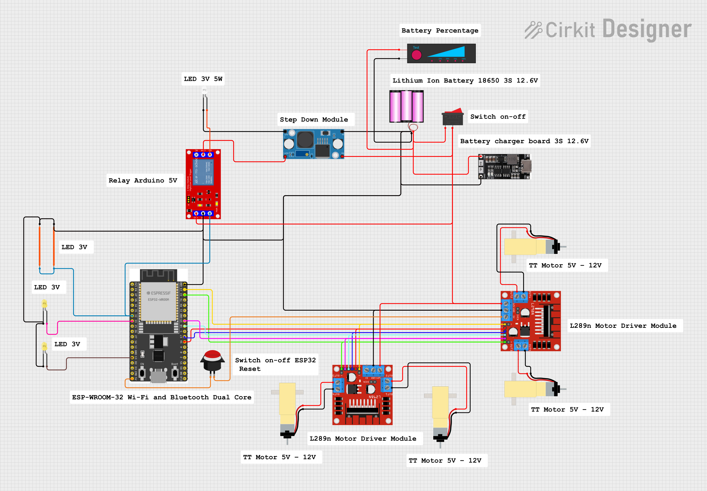
ESP32 and L298N Motor Driver-Based Bluetooth-Controlled Robotic Car with LED Indicators
Circuit Documentation
Summary
This document provides a detailed overview of a circuit designed to control motors and LEDs using an ESP32 microcontroller. The circuit includes various components such as motor drivers, relays, LEDs, a step-down module, and a battery. The ESP32 microcontroller is programmed to control the motors and LEDs based on input from a gamepad.
Component List
L298N DC Motor Driver
- Description: Dual H-Bridge motor driver for controlling DC motors.
- Pins: OUT1, OUT2, 12V, GND, 5V, OUT3, OUT4, 5V-ENA-JMP-I, 5V-ENA-JMP-O, +5V-J1, +5V-J2, ENA, IN1, IN2, IN3, IN4, ENB
ESP32 Wroom Dev Kit
- Description: Microcontroller with Wi-Fi and Bluetooth capabilities.
- Pins: 3V3, EN, VP, VN, GPIO 34, GPIO 35, GPIO 32, GPIO 33, GPIO 25, GPIO 26, GPIO 27, GPIO 14, GND, GPIO 13, SD2, SD3, CMD, V5, GPIO 23, GPIO 22, TXD, RXD, GPIO 21, GPIO 19, GPIO 18, GPIO 5, GPIO 17, GPIO 16, GPIO 4, GPIO 0, GPIO 2, GPIO 15, SD1, SD0, CLK
1 Channel 5V Relay Module
- Description: Relay module for switching high voltage devices.
- Pins: VCC+, VCC- (GND), IN, N.O., COM, N.C.
Battery 12V
- Description: Power source for the circuit.
- Pins: +, -
LED Filament 3V
- Description: LED filament for visual indication.
- Pins: GND, Vcc
LED: Two Pin (yellow)
- Description: Yellow LED for visual indication.
- Pins: cathode, anode
LM2596 Step Down Module
- Description: Step-down voltage regulator.
- Pins: OUT-, OUT+, IN-, IN+
LED: Two Pin (white)
- Description: White LED for visual indication.
- Pins: cathode, anode
Hobby Gearmotor with 48:1 Gearbox
- Description: DC motor with gearbox for precise control.
- Pins: pin 1, pin 2
18650 Lithium Ion Charger
- Description: Charger for 18650 lithium-ion batteries.
- Pins: V IN, GND, OUT, IN, BAT IN, BAT GND
Rocker Switch
- Description: Switch for controlling power.
- Pins: 1, 2
Battery Level
- Description: Battery level indicator.
- Pins: +, -
Push Button Round
- Description: Push button for user input.
- Pins: leg0, leg1
Wiring Details
L298N DC Motor Driver
- OUT1 connected to Hobby Gearmotor with 48:1 Gearbox pin 1
- OUT2 connected to Hobby Gearmotor with 48:1 Gearbox pin 2
- 12V connected to L298N DC Motor Driver 12V, 1 Channel 5V Relay Module VCC+, LM2596 Step Down Module IN+, Rocker Switch pin 2
- GND connected to LED: Two Pin (yellow) cathode, L298N DC Motor Driver GND, ESP32 Wroom Dev Kit GND, Battery 12V -, 18650 Lithium Ion Charger BAT GND, 1 Channel 5V Relay Module VCC- (GND), Battery Level -, LED Filament 3V GND, LM2596 Step Down Module IN-, LED Filament 3V GND
- 5V connected to Push Button Round leg1
- OUT3 connected to Hobby Gearmotor with 48:1 Gearbox pin 2
- OUT4 connected to Hobby Gearmotor with 48:1 Gearbox pin 1
- ENA connected to L298N DC Motor Driver ENA, ESP32 Wroom Dev Kit GPIO 23
- IN1 connected to L298N DC Motor Driver IN1, ESP32 Wroom Dev Kit GPIO 16
- IN2 connected to L298N DC Motor Driver IN2, ESP32 Wroom Dev Kit GPIO 17
- IN3 connected to L298N DC Motor Driver IN3, ESP32 Wroom Dev Kit GPIO 18
- IN4 connected to L298N DC Motor Driver IN4, ESP32 Wroom Dev Kit GPIO 19
- ENB connected to L298N DC Motor Driver ENB, ESP32 Wroom Dev Kit GPIO 22
ESP32 Wroom Dev Kit
- GPIO 32 connected to 1 Channel 5V Relay Module IN, LED Filament 3V Vcc, LED Filament 3V Vcc
- GPIO 33 connected to LED: Two Pin (yellow) anode
- GPIO 13 connected to LED: Two Pin (yellow) anode
- V5 connected to Push Button Round leg0
1 Channel 5V Relay Module
- N.O. connected to LED: Two Pin (white) anode
- COM connected to LM2596 Step Down Module OUT+
Battery 12V
- + connected to 18650 Lithium Ion Charger BAT IN, Battery Level +, Rocker Switch pin 1
LED: Two Pin (white)
- cathode connected to LM2596 Step Down Module OUT-
L298N DC Motor Driver (Second Instance)
- OUT1 connected to Hobby Gearmotor with 48:1 Gearbox pin 1
- OUT2 connected to Hobby Gearmotor with 48:1 Gearbox pin 2
- OUT3 connected to Hobby Gearmotor with 48:1 Gearbox pin 2
- OUT4 connected to Hobby Gearmotor with 48:1 Gearbox pin 1
Code Documentation
ESP32 Wroom Dev Kit Code
#define CUSTOM_SETTINGS
#define INCLUDE_GAMEPAD_MODULE
#include <DabbleESP32.h>

// Motor control pins
int enableRightMotor = 22;
int rightMotorPin1 = 16;
int rightMotorPin2 = 17;
int enableLeftMotor = 23;
int leftMotorPin1 = 18;
int leftMotorPin2 = 19;

// Relay control pins
int relayPin1 = 32;  // Relay for Triangle button (on/off light)
int relayPin2 = 33;  // Relay for Square button (on/off light)
int relayPin3 = 13;  // Relay for Circle button (on/off light)

#define MAX_MOTOR_SPEED 255
const int PWMFreq = 1000; /* 1 KHz */
const int PWMResolution = 8;
const int rightMotorPWMSpeedChannel = 4;
const int leftMotorPWMSpeedChannel = 5;

bool relay1State = false;  // State for Relay 1 (Triangle)
bool relay2State = false;  // State for Relay 2 (Square)
bool relay3State = false;  // State for Relay 3 (Circle)

void rotateMotor(int rightMotorSpeed, int leftMotorSpeed)
{
  // Right motor control
  if (rightMotorSpeed < 0)
  {
    digitalWrite(rightMotorPin1, LOW);
    digitalWrite(rightMotorPin2, HIGH);
  }
  else if (rightMotorSpeed > 0)
  {
    digitalWrite(rightMotorPin1, HIGH);
    digitalWrite(rightMotorPin2, LOW);
  }
  else
  {
    digitalWrite(rightMotorPin1, LOW);
    digitalWrite(rightMotorPin2, LOW);
  }

  // Left motor control
  if (leftMotorSpeed < 0)
  {
    digitalWrite(leftMotorPin1, LOW);
    digitalWrite(leftMotorPin2, HIGH);
  }
  else if (leftMotorSpeed > 0)
  {
    digitalWrite(leftMotorPin1, HIGH);
    digitalWrite(leftMotorPin2, LOW);
  }
  else
  {
    digitalWrite(leftMotorPin1, LOW);
    digitalWrite(leftMotorPin2, LOW);
  }

  // Set PWM speed for motors
  ledcWrite(rightMotorPWMSpeedChannel, abs(rightMotorSpeed));
  ledcWrite(leftMotorPWMSpeedChannel, abs(leftMotorSpeed));

  // Control relays based on motor direction
  if (rightMotorSpeed >