
ESP32 and INMP441 Smart Audio System with Pushbutton Control and LED Indicators
View and Edit Project In Cirkit Designer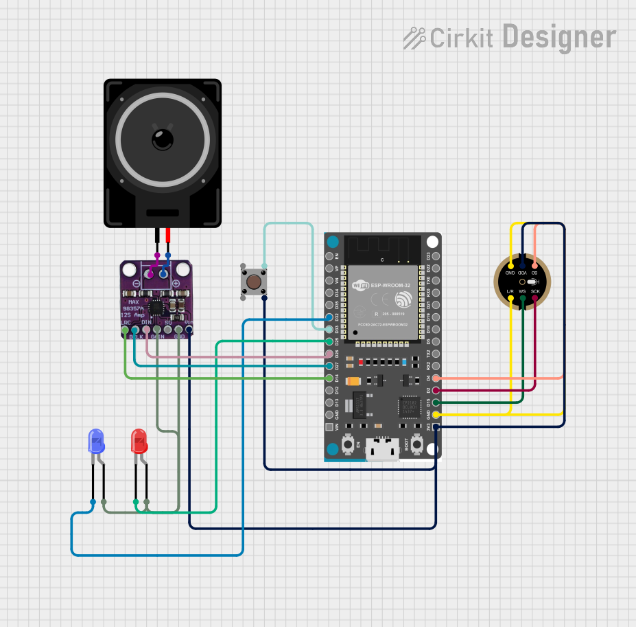
Circuit Documentation
Summary
This document provides a detailed overview of a circuit that includes an ESP32 Devkit V1 microcontroller, an INMP441 microphone, a Max98357 amplifier, a loudspeaker, pushbutton, and two LEDs (red and blue). The circuit is designed to capture audio input, process it, and output it through a loudspeaker, with additional user interaction via a pushbutton and visual feedback through LEDs.
Component List
INMP441 FRONT MIC
- Description: Digital MEMS microphone
- Pins: L/R, WS, SCK, SD, VDD, GND
Pushbutton
- Description: Simple pushbutton switch
- Pins: Pin 3 (out), Pin 4 (out), Pin 1 (in), Pin 2 (in)
LED: Two Pin (red)
- Description: Red LED
- Pins: cathode, anode
LED: Two Pin (blue)
- Description: Blue LED
- Pins: cathode, anode
ESP32 Devkit V1
- Description: Microcontroller with Wi-Fi and Bluetooth capabilities
- Pins: 3V3, GND, D15, D2, D4, RX2, TX2, D5, D18, D19, D21, RX0, TX0, D22, D23, EN, VP, VN, D34, D35, D32, D33, D25, D26, D27, D14, D12, D13, VIN
Loudspeaker
- Description: Audio output device
- Pins: pin1, pin2
Max98357
- Description: Class D amplifier
- Pins: LRC, BLCK, DIN, GAIN, SD, GND, VIN, -, +
Wiring Details
INMP441 FRONT MIC
- VDD connected to Pushbutton Pin 4 (out)
- VDD connected to Max98357 VIN
- VDD connected to ESP32 Devkit V1 3V3
- L/R connected to INMP441 FRONT MIC GND
- L/R connected to ESP32 Devkit V1 GND
- WS connected to ESP32 Devkit V1 D15
- SCK connected to ESP32 Devkit V1 D2
- SD connected to ESP32 Devkit V1 D4
Pushbutton
- Pin 4 (out) connected to INMP441 FRONT MIC VDD
- Pin 4 (out) connected to Max98357 VIN
- Pin 4 (out) connected to ESP32 Devkit V1 3V3
- Pin 3 (out) connected to ESP32 Devkit V1 D33
LED: Two Pin (red)
- cathode connected to ESP32 Devkit V1 D25
- anode connected to Max98357 GAIN
- anode connected to Max98357 GND
LED: Two Pin (blue)
- cathode connected to ESP32 Devkit V1 D32
- anode connected to Max98357 GAIN
- anode connected to Max98357 GND
ESP32 Devkit V1
- 3V3 connected to Pushbutton Pin 4 (out)
- 3V3 connected to INMP441 FRONT MIC VDD
- 3V3 connected to Max98357 VIN
- GND connected to INMP441 FRONT MIC L/R
- GND connected to INMP441 FRONT MIC GND
- D15 connected to INMP441 FRONT MIC WS
- D2 connected to INMP441 FRONT MIC SCK
- D4 connected to INMP441 FRONT MIC SD
- D32 connected to LED: Two Pin (blue) cathode
- D33 connected to Pushbutton Pin 3 (out)
- D25 connected to LED: Two Pin (red) cathode
- D26 connected to Max98357 DIN
- D27 connected to Max98357 BLCK
- D14 connected to Max98357 LRC
Loudspeaker
- pin1 connected to Max98357 -
- pin2 connected to Max98357 +
Max98357
- VIN connected to Pushbutton Pin 4 (out)
- VIN connected to INMP441 FRONT MIC VDD
- VIN connected to ESP32 Devkit V1 3V3
- DIN connected to ESP32 Devkit V1 D26
- BLCK connected to ESP32 Devkit V1 D27
- LRC connected to ESP32 Devkit V1 D14
- - connected to Loudspeaker pin1
- + connected to Loudspeaker pin2
- GAIN connected to LED: Two Pin (blue) anode
- GAIN connected to LED: Two Pin (red) anode
- GND connected to LED: Two Pin (blue) anode
- GND connected to LED: Two Pin (red) anode
Documented Code
ESP32 Devkit V1 Code
void setup() {
  // put your setup code here, to run once:

}

void loop() {
  // put your main code here, to run repeatedly:

}
INMP441 FRONT MIC Code
void setup() {
  // put your setup code here, to run once:

}

void loop() {
  // put your main code here, to run repeatedly:

}
This documentation provides a comprehensive overview of the circuit, including the components used, their connections, and the code running on the microcontrollers.