
Arduino UNO Controlled Multi-Servo System with Push Button Interface
View and Edit Project In Cirkit Designer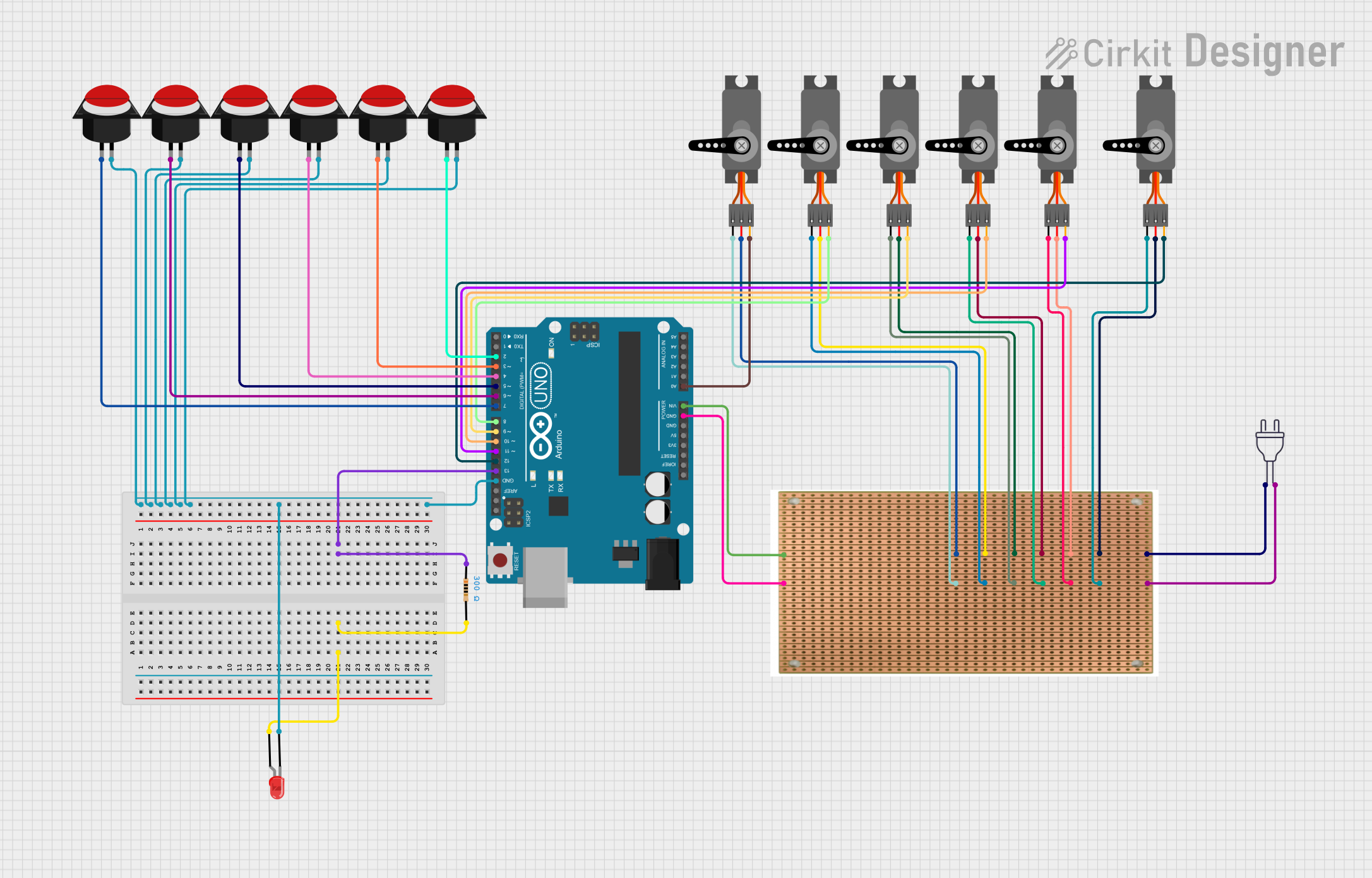
Circuit Documentation
Summary
This circuit involves an Arduino UNO microcontroller, multiple servos, push buttons, an LED, a resistor, and a power supply. The Arduino UNO controls the servos and reads the state of the push buttons. The LED is connected through a resistor to one of the digital pins of the Arduino. The power supply is connected to a stripboard, which distributes power to the servos.
Component List
Arduino UNO
- Description: A microcontroller board based on the ATmega328P.
- Pins: UNUSED, IOREF, Reset, 3.3V, 5V, GND, Vin, A0, A1, A2, A3, A4, A5, SCL, SDA, AREF, D13, D12, D11, D10, D9, D8, D7, D6, D5, D4, D3, D2, D1, D0
Servo
- Description: A motor that can be positioned at various angles.
- Pins: GND, VCC, PWM
Push Button Round
- Description: A simple push button switch.
- Pins: leg0, leg1
LED: Two Pin (red)
- Description: A red light-emitting diode.
- Pins: cathode, anode
Resistor
- Description: A 300 Ohms resistor.
- Pins: pin1, pin2
Power 220V
- Description: A 220V power supply.
- Pins: hot wire, neutral wire
Stripboard
- Description: A board used for prototyping electronic circuits.
- Pins: None
Wiring Details
Arduino UNO
- D13: Connected to Resistor pin1
- D12: Connected to Servo PWM
- D11: Connected to Servo PWM
- D10: Connected to Servo PWM
- D9: Connected to Servo PWM
- D8: Connected to Servo PWM
- D7: Connected to Push Button Round leg0
- D6: Connected to Push Button Round leg0
- D5: Connected to Push Button Round leg0
- D4: Connected to Push Button Round leg0
- D3: Connected to Push Button Round leg0
- D2: Connected to Push Button Round leg0
- A0: Connected to Servo PWM
- GND: Connected to LED cathode, Push Button Round leg1, Stripboard
- Vin: Connected to Stripboard
Servo
- PWM: Connected to Arduino UNO A0, D12, D11, D10, D9, D8
- VCC: Connected to Stripboard
- GND: Connected to Stripboard
Push Button Round
- leg0: Connected to Arduino UNO D7, D6, D5, D4, D3, D2
- leg1: Connected to LED cathode, Arduino UNO GND
LED: Two Pin (red)
- anode: Connected to Resistor pin2
- cathode: Connected to Push Button Round leg1, Arduino UNO GND
Resistor
- pin1: Connected to Arduino UNO D13
- pin2: Connected to LED anode
Power 220V
- hot wire: Connected to Stripboard
- neutral wire: Connected to Stripboard
Stripboard
- Connections:
- Connected to Arduino UNO GND, Vin
- Connected to Servo VCC, GND
- Connected to Power 220V hot wire, neutral wire
Code Documentation
Arduino UNO Code
void setup() {
  // put your setup code here, to run once:

}

void loop() {
  // put your main code here, to run repeatedly:

}
This code is a basic template for the Arduino UNO. The setup() function is where you initialize your components and settings, and the loop() function is where the main logic of your program runs repeatedly.
This documentation provides a comprehensive overview of the circuit, including a summary, detailed component list, wiring details, and the code used in the microcontroller.