
NodeMCU ESP8266-Based Smart Irrigation and Environmental Monitoring System
View and Edit Project In Cirkit Designer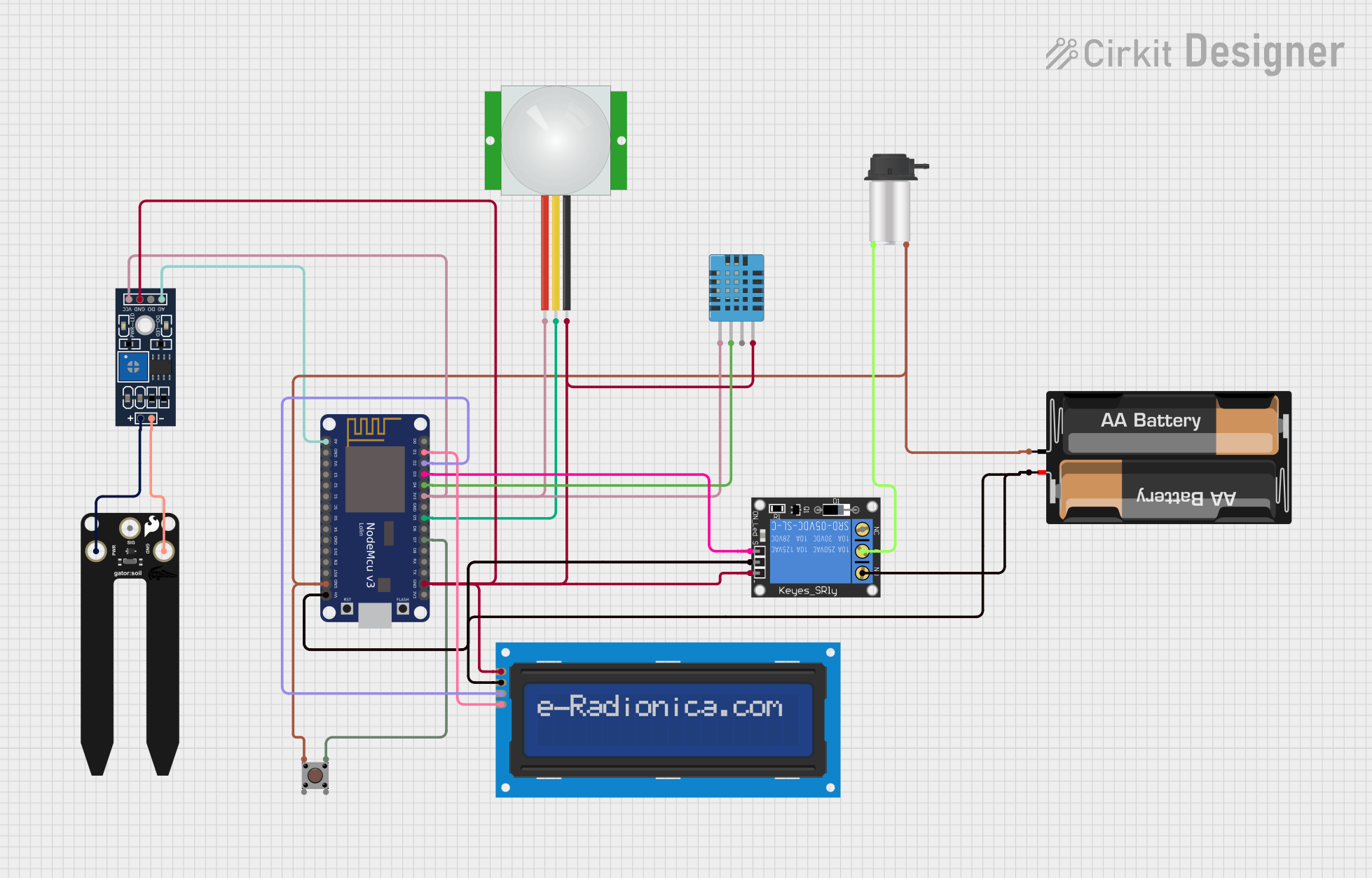
Circuit Documentation
Summary
This circuit is designed to interface various sensors and actuators with a NodeMCU V3 ESP8266 microcontroller. The sensors include a soil moisture sensor (SparkFun gator:soil), a PIR motion sensor, a DHT11 humidity and temperature sensor, and a YL-83 rain sensor. The circuit also includes a pushbutton, an LCD screen for display, a 1-channel relay to control power to a peristaltic pump, and a 2 x AA battery mount to provide power. The NodeMCU V3 ESP8266 serves as the central processing unit, reading sensor data, controlling the relay, and displaying information on the LCD screen.
Component List
SparkFun gator:soil
- Soil moisture sensor
- Pins: VCC, GND, SIG
NodeMCU V3 ESP8266
- Microcontroller with WiFi capability
- Pins: A0, GND, VU, S3, S2, S1, SC, S0, SK, 3V3, EN, RST, Vin, D0, D1, D2, D3, D4, D5, D6, D7, D8, RX, TX
Pushbutton
- Standard pushbutton switch
- Pins: Pin 3 (out), Pin 4 (out), Pin 1 (in), Pin 2 (in)
PIR Sensor
- Passive Infrared Sensor for motion detection
- Pins: VDD, SIG, GND
DHT11 Humidity and Temperature Sensor
- Sensor for measuring ambient humidity and temperature
- Pins: VDD, DATA, NULL, GND
1-Channel Relay (5V 10A)
- Electromechanical switch controlled by an electric signal
- Pins: NC, signal, C, power, NO, ground
2 x AA Battery Mount
- Power source for the circuit
- Pins: -, +
Peristaltic Pump
- Pump for controlled fluid movement
- Pins: Coil1, Coil2
LCD Screen 16x2 I2C
- Alphanumeric liquid crystal display with I2C interface
- Pins: SCL, SDA, VCC, GND
YL-83 Rain Sensor - Control Board
- Sensor for detecting rainwater
- Pins: VCC, GND, DO, AO, POS, NEG
Wiring Details
SparkFun gator:soil
- VCC connected to YL-83 Rain Sensor - Control Board POS
- GND connected to YL-83 Rain Sensor - Control Board NEG
- SIG not connected
NodeMCU V3 ESP8266
- A0 connected to YL-83 Rain Sensor - Control Board AO
- GND connected to 2 x AA Battery Mount -, Peristaltic Pump Coil2, Pushbutton Pin 1 (in), and common ground net
- Vin connected to 1-Channel Relay (5V 10A) power
- D0 not connected
- D1 connected to LCD screen 16x2 I2C SCL
- D2 connected to LCD screen 16x2 I2C SDA
- D3 connected to 1-Channel Relay (5V 10A) signal
- D4 connected to DHT11 Humidity and Temperature Sensor DATA
- D5 connected to PIR Sensor SIG
- D6 not connected
- D7 connected to Pushbutton Pin 3 (out)
- D8 not connected
- RX not connected
- TX not connected
- 3V3 connected to YL-83 Rain Sensor - Control Board VCC, PIR Sensor VDD, and DHT11 Humidity and Temperature Sensor VDD
Pushbutton
- Pin 3 (out) connected to NodeMCU V3 ESP8266 D7
- Pin 1 (in) connected to 2 x AA Battery Mount -
PIR Sensor
- VDD connected to NodeMCU V3 ESP8266 3V3
- SIG connected to NodeMCU V3 ESP8266 D5
- GND connected to common ground net
DHT11 Humidity and Temperature Sensor
- VDD connected to NodeMCU V3 ESP8266 3V3
- DATA connected to NodeMCU V3 ESP8266 D4
- GND connected to common ground net
1-Channel Relay (5V 10A)
- NC not connected
- Signal connected to NodeMCU V3 ESP8266 D3
- C connected to Peristaltic Pump Coil1
- Power connected to 2 x AA Battery Mount +
- NO connected to 2 x AA Battery Mount +
- Ground connected to common ground net
2 x AA Battery Mount
-
- connected to NodeMCU V3 ESP8266 GND, Peristaltic Pump Coil2, Pushbutton Pin 1 (in)
-
- connected to 1-Channel Relay (5V 10A) power, NodeMCU V3 ESP8266 Vin, LCD screen 16x2 I2C VCC
Peristaltic Pump
- Coil1 connected to 1-Channel Relay (5V 10A) C
- Coil2 connected to 2 x AA Battery Mount -
LCD Screen 16x2 I2C
- SCL connected to NodeMCU V3 ESP8266 D1
- SDA connected to NodeMCU V3 ESP8266 D2
- VCC connected to 2 x AA Battery Mount +
- GND connected to common ground net
YL-83 Rain Sensor - Control Board
- VCC connected to NodeMCU V3 ESP8266 3V3
- GND connected to common ground net
- DO not connected
- AO connected to NodeMCU V3 ESP8266 A0
- POS connected to SparkFun gator:soil VCC
- NEG connected to SparkFun gator:soil GND
Documented Code
No code was provided for the microcontroller. The documentation of the code would typically include a description of the functionality, setup, and main loop, along with comments explaining the purpose of each section of the code. Since no code is available, this section cannot be completed. If code becomes available, it should be documented here following best practices for code documentation and readability.