Cirkit Designer
Your all-in-one circuit design IDE
Home /
Project Documentation
Arduino UNO-Based Load Cell Weight Measurement System with TFT Display
Circuit Documentation
Summary
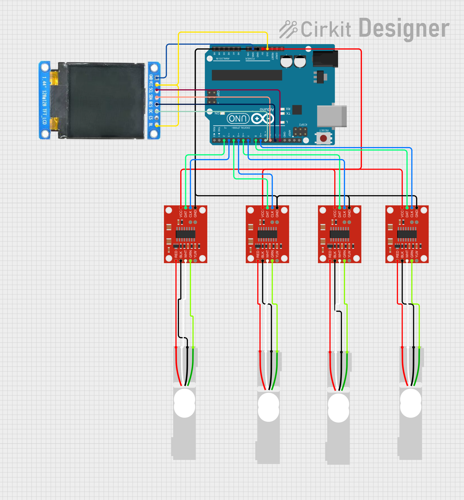
This circuit involves an Arduino UNO microcontroller interfacing with multiple load cells through SparkFun Load Cell Amplifiers (HX711) and displaying data on an ST7735 128x128 1.44 TFT I2C Color display. The load cells measure weight, and the data is amplified and sent to the Arduino, which processes the data and displays it on the TFT screen.
Component List
Arduino UNO
- Description: A microcontroller board based on the ATmega328P.
- Pins: UNUSED, IOREF, Reset, 3.3V, 5V, GND, Vin, A0, A1, A2, A3, A4, A5, SCL, SDA, AREF, D13, D12, D11, D10, D9, D8, D7, D6, D5, D4, D3, D2, D1, D0
Load Cell - Red/white/black/green
- Description: A sensor used to measure weight.
- Pins: E+, A-, E-, A+
SparkFun Load Cell Amplifier - HX711
- Description: An amplifier for load cells, used to convert the small signals from the load cells into a form that can be read by the Arduino.
- Pins: GND, CLK, DAT, VCC, YLW, GRN, WHT, BLK, RED, B-, B+
ST7735 128x128 1.44 TFT I2C Color
- Description: A color display module with I2C interface.
- Pins: BL, C5, DC, RES, SDA, SCL, GND, VCC
Wiring Details
Arduino UNO
- 3.3V connected to VCC and BL of ST7735 128x128 1.44 TFT I2C Color.
- 5V connected to VCC of all SparkFun Load Cell Amplifiers (HX711).
- GND connected to GND of all SparkFun Load Cell Amplifiers (HX711) and GND of ST7735 128x128 1.44 TFT I2C Color.
- D13 connected to SCL of ST7735 128x128 1.44 TFT I2C Color.
- D12 connected to RES of ST7735 128x128 1.44 TFT I2C Color.
- D11 connected to SDA of ST7735 128x128 1.44 TFT I2C Color.
- D10 connected to DC of ST7735 128x128 1.44 TFT I2C Color.
- D9 connected to CLK of one SparkFun Load Cell Amplifier (HX711).
- D8 connected to DAT of one SparkFun Load Cell Amplifier (HX711).
- D7 connected to CLK of another SparkFun Load Cell Amplifier (HX711).
- D6 connected to DAT of another SparkFun Load Cell Amplifier (HX711).
- D5 connected to CLK of another SparkFun Load Cell Amplifier (HX711).
- D4 connected to DAT of another SparkFun Load Cell Amplifier (HX711).
- D3 connected to CLK of another SparkFun Load Cell Amplifier (HX711).
- D2 connected to DAT of another SparkFun Load Cell Amplifier (HX711).
Load Cell - Red/white/black/green
- E+ connected to RED of corresponding SparkFun Load Cell Amplifier (HX711).
- A- connected to WHT of corresponding SparkFun Load Cell Amplifier (HX711).
- E- connected to BLK of corresponding SparkFun Load Cell Amplifier (HX711).
- A+ connected to GRN of corresponding SparkFun Load Cell Amplifier (HX711).
SparkFun Load Cell Amplifier - HX711
- VCC connected to 5V of Arduino UNO.
- GND connected to GND of Arduino UNO.
- CLK connected to respective digital pins (D9, D7, D5, D3) of Arduino UNO.
- DAT connected to respective digital pins (D8, D6, D4, D2) of Arduino UNO.
- RED connected to E+ of corresponding Load Cell.
- WHT connected to A- of corresponding Load Cell.
- BLK connected to E- of corresponding Load Cell.
- GRN connected to A+ of corresponding Load Cell.
ST7735 128x128 1.44 TFT I2C Color
- BL connected to 3.3V of Arduino UNO.
- VCC connected to 3.3V of Arduino UNO.
- GND connected to GND of Arduino UNO.
- SCL connected to D13 of Arduino UNO.
- RES connected to D12 of Arduino UNO.
- SDA connected to D11 of Arduino UNO.
- DC connected to D10 of Arduino UNO.
Documented Code
Arduino UNO Code (sketch.ino)
void setup() {
  // put your setup code here, to run once:

}

void loop() {
  // put your main code here, to run repeatedly:

}
Additional Documentation (documentation.txt)
This documentation provides a comprehensive overview of the circuit, including a summary, detailed component list, wiring details, and the code used in the Arduino UNO.