
ESP32 Bluetooth-Controlled Dual Joystick Motor Driver System
View and Edit Project In Cirkit Designer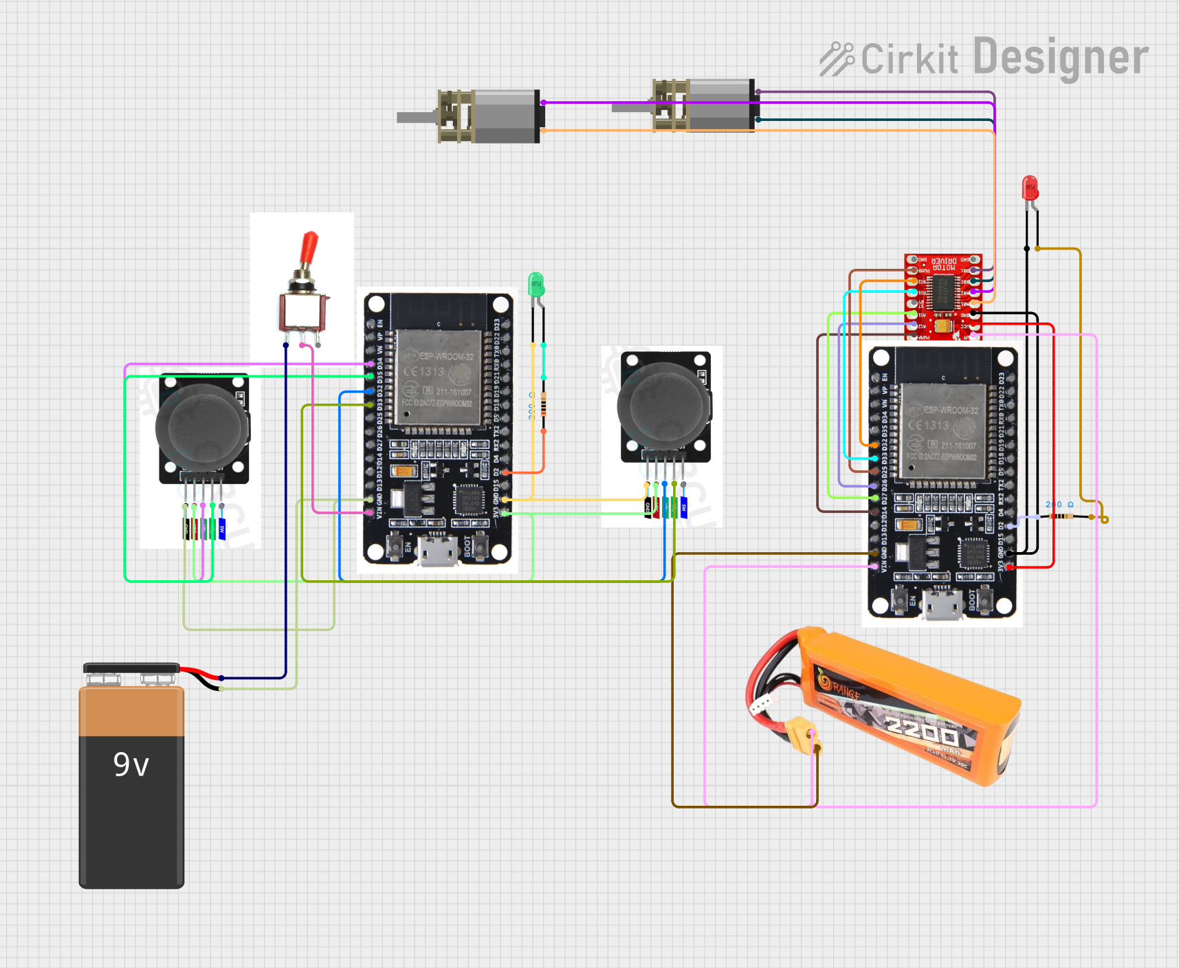
Circuit Documentation
Summary
This circuit involves two ESP32 microcontrollers, joystick modules, a toggle switch, motor drivers, DC motors, LEDs, resistors, and batteries. The primary function of the circuit is to read joystick inputs and control DC motors via Bluetooth communication between the two ESP32 microcontrollers. The circuit also includes LEDs for visual indication.
Component List
Joystick Module
- Pins: SW, VRY, VRX, VCC, GND
- Description: Used to capture analog input from the joystick movements.
Toggle Switch
- Pins: Vcc, Sig, Gnd
- Description: Used to toggle the power supply to the ESP32 microcontroller.
TB6612FNG Motor Driver
- Pins: GND, B01, B02, A02, A01, VCC, VM, PWMB, BI2, BI1, STBY, AI1, AI2, PWMA
- Description: Used to control the DC motors based on the signals received from the ESP32 microcontroller.
ESP32
- Pins: EN, VP, VN, D34, D35, D32, D33, D25, D26, D27, D14, D12, D13, GND, VIN, 3V3, D15, D2, D4, RX2, TX2, D5, D18, D19, D21, RX0, TX0, D22, D23, BOOT
- Description: Microcontroller used for Bluetooth communication and control logic.
LED: Two Pin (green)
- Pins: cathode, anode
- Description: Used for visual indication.
LED: Two Pin (red)
- Pins: cathode, anode
- Description: Used for visual indication.
Lipo Battery 2200mAH 30c
- Pins: VCC, GND
- Description: Power supply for the motor driver and ESP32 microcontroller.
Resistor (200 Ohms)
- Pins: pin1, pin2
- Description: Used to limit current to the LEDs.
DC Mini Metal Gear Motor
- Pins: IN1, IN2
- Description: Used to drive mechanical components based on control signals.
9V Battery
- Pins: -, +
- Description: Power supply for the toggle switch and ESP32 microcontroller.
Wiring Details
Joystick Module 1
- VRY connected to ESP32 D35
- VRX connected to ESP32 D34
- VCC connected to ESP32 3V3
- GND connected to ESP32 GND
Joystick Module 2
- VRY connected to ESP32 D33
- VRX connected to ESP32 D32
- VCC connected to ESP32 3V3
- GND connected to ESP32 GND
Toggle Switch
- Vcc connected to 9V Battery +
- Sig connected to ESP32 VIN
- Gnd connected to ESP32 GND
TB6612FNG Motor Driver
- B01 connected to DC Mini Metal Gear Motor IN2
- B02 connected to DC Mini Metal Gear Motor IN1
- A02 connected to DC Mini Metal Gear Motor IN2
- A01 connected to DC Mini Metal Gear Motor IN1
- GND connected to ESP32 GND
- VCC connected to ESP32 3V3
- VM connected to Lipo Battery 2200mAH 30c VCC
- PWMB connected to ESP32 D25
- BI2 connected to ESP32 D32
- BI1 connected to ESP32 D33
- AI1 connected to ESP32 D27
- AI2 connected to ESP32 D26
- PWMA connected to ESP32 D14
LED: Two Pin (green)
- cathode connected to ESP32 GND
- anode connected to Resistor pin2
LED: Two Pin (red)
- cathode connected to TB6612FNG Motor Driver GND
- anode connected to Resistor pin2
Lipo Battery 2200mAH 30c
- VCC connected to TB6612FNG Motor Driver VM
- GND connected to ESP32 GND
Resistor 1 (200 Ohms)
- pin1 connected to ESP32 D2
- pin2 connected to LED: Two Pin (green) anode
Resistor 2 (200 Ohms)
- pin1 connected to ESP32 D2
- pin2 connected to LED: Two Pin (red) anode
DC Mini Metal Gear Motor 1
- IN2 connected to TB6612FNG Motor Driver B01
- IN1 connected to TB6612FNG Motor Driver B02
DC Mini Metal Gear Motor 2
- IN2 connected to TB6612FNG Motor Driver A02
- IN1 connected to TB6612FNG Motor Driver A01
9V Battery
- + connected to Toggle Switch Vcc
- - connected to ESP32 GND
Code Documentation
ESP32 (Transmitter)
#include <BluetoothSerial.h>

BluetoothSerial SerialBT;

void setup() {
  pinMode(2, OUTPUT); // LED indicator
  Serial.begin(115200);
  SerialBT.begin("ESP32_Emisor"); // Bluetooth device name
  Serial.println("The Bluetooth device is ready to pair");
}

void loop() {
  int joy1X = analogRead(34);
  int joy1Y = analogRead(35);
  int joy2X = analogRead(32);
  int joy2Y = analogRead(33);

  String message = String(joy1X) + "," + String(joy1Y) + "," + String(joy2X) + "," + String(joy2Y);
  SerialBT.println(message);

  digitalWrite(2, HIGH); // Turn on the LED
  delay(100);
  digitalWrite(2, LOW); // Turn off the LED
  delay(100);
}
ESP32 (Receiver)
#include <BluetoothSerial.h>

BluetoothSerial SerialBT;

const int PWMA = 14;
const int AIN1 = 27;
const int AIN2 = 26;
const int PWMB = 25;
const int BIN1 = 33;
const int BIN2 = 32;

void setup() {
  pinMode(PWMA, OUTPUT);
  pinMode(AIN1, OUTPUT);
  pinMode(AIN2, OUTPUT);
  pinMode(PWMB, OUTPUT);
  pinMode(BIN1, OUTPUT);
  pinMode(BIN2, OUTPUT);
  pinMode(2, OUTPUT); // LED indicator

  Serial.begin(115200);
  SerialBT.begin("ESP32_Receptor");
  Serial.println("The Bluetooth device is ready to receive");
}

void loop() {
   if (SerialBT.available()) {
    String message = SerialBT.readStringUntil('\n');
    int commaCount = message.length() - message.replace(",", "").length();

    if (commaCount == 3) { // Ensure there are exactly 3 commas
      int joy1X = message.substring(0, message.indexOf(',')).toInt();
      message = message.substring(message.indexOf(',') + 1);
      int joy1Y = message.substring(0, message.indexOf(',')).toInt();
      message = message.substring(message.indexOf(',') + 1);
      int joy2X = message.substring(0, message.indexOf(',')).toInt();
      message = message.substring(message.indexOf(',') + 1);
      int joy2Y = message.toInt();

      // Example motor control logic
      analogWrite(PWMA, joy1X);
      digitalWrite(AIN1, joy1Y > 512 ? HIGH : LOW);
      digitalWrite(AIN2, joy1Y <= 512 ? HIGH : LOW);

      analogWrite(PWMB, joy2X);
      digitalWrite(BIN1, joy2Y > 512 ? HIGH : LOW);
      digitalWrite(BIN2, joy2Y <= 512 ? HIGH : LOW);

      digitalWrite(2, HIGH); // Turn on the LED
      delay(100);
      digitalWrite(2, LOW); // Turn off the LED
    } else {
      Serial.println("Error: Malformed message");
    }

    // Motor control logic based on joystick values
    // Add logic to control motors here

    digitalWrite(2, HIGH); // Turn on the LED
    delay(100);
    digitalWrite(2, LOW); // Turn off the LED
  }
}
This documentation provides a comprehensive overview of the circuit, including a summary, component list, wiring details, and code documentation.