
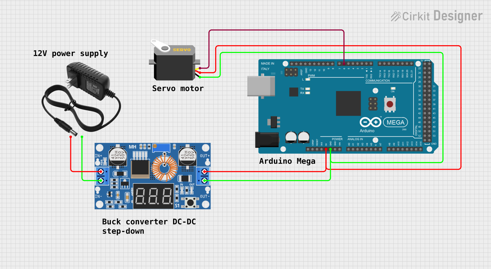
Circuit Documentation
Summary
The circuit in question is designed to control a servo motor using an Arduino Mega 2560 microcontroller. The servo is powered by a regulated 5V supply, which is stepped down from a 12V power source using an XL4015 5A DC Buck Step-down converter. The Arduino Mega 2560 provides a PWM signal to control the position of the servo. The circuit is suitable for applications requiring precise control of a servo motor, such as robotics or automated systems.
Component List
Servo
- Pins: gnd, vcc, pulse
- Description: A servo motor capable of precise position control through PWM signals.
12v Power Supply
- Pins: +, -
- Description: A power supply unit that provides a 12V output.
XL4015 5A DC Buck Step-down Converter
- Pins: Output +, Output -, Input +, Input -
- Description: A DC-DC step-down (buck) converter that steps down the voltage from 12V to a regulated 5V output.
Arduino Mega 2560
- Pins: Multiple digital and analog pins, including IOREF, RESET, 3V3, 5V, GND, VIN, PWM, AREF, SDA, SCL, etc.
- Description: A microcontroller board based on the ATmega2560, with numerous I/O pins for interfacing with various sensors, actuators, and other electronic components.
Wiring Details
Servo
- gnd: Connected to the ground (GND) of the Arduino Mega 2560 and the Output - of the XL4015 step-down converter.
- vcc: Connected to the 5V output of the Arduino Mega 2560 and the Output + of the XL4015 step-down converter.
- pulse: Connected to the D6 PWM pin of the Arduino Mega 2560 to receive PWM control signals.
12v Power Supply
- +: Connected to the Input + of the XL4015 step-down converter.
- -: Connected to the Input - of the XL4015 step-down converter.
XL4015 5A DC Buck Step-down Converter
- Output +: Connected to the 5V pin of the Arduino Mega 2560 and the vcc of the Servo.
- Output -: Connected to the GND of the Arduino Mega 2560 and the gnd of the Servo.
- Input +: Connected to the + of the 12v power supply.
- Input -: Connected to the - of the 12v power supply.
Arduino Mega 2560
- 5V: Connected to the Output + of the XL4015 step-down converter and the vcc of the Servo.
- GND: Connected to the Output - of the XL4015 step-down converter and the gnd of the Servo.
- D6 PWM: Connected to the pulse pin of the Servo to provide PWM control signals.
Documented Code
Arduino Mega 2560 Code (sketch.ino)
void setup() {
  // put your setup code here, to run once:

}

void loop() {
  // put your main code here, to run repeatedly:

}
Note: The provided code for the Arduino Mega 2560 is a template with empty setup and loop functions. To control the servo, code needs to be added to generate PWM signals on the D6 PWM pin.
Additional Notes
- The 12v power supply code provided is empty and not applicable to the power supply as it does not have programmable features.
- The documentation for the Arduino Mega 2560 is also empty and should be filled with relevant information as the code for controlling the servo is developed.