Arduino UNO Controlled Quadcopter with GPS and MPU-6050
Circuit Documentation
Summary
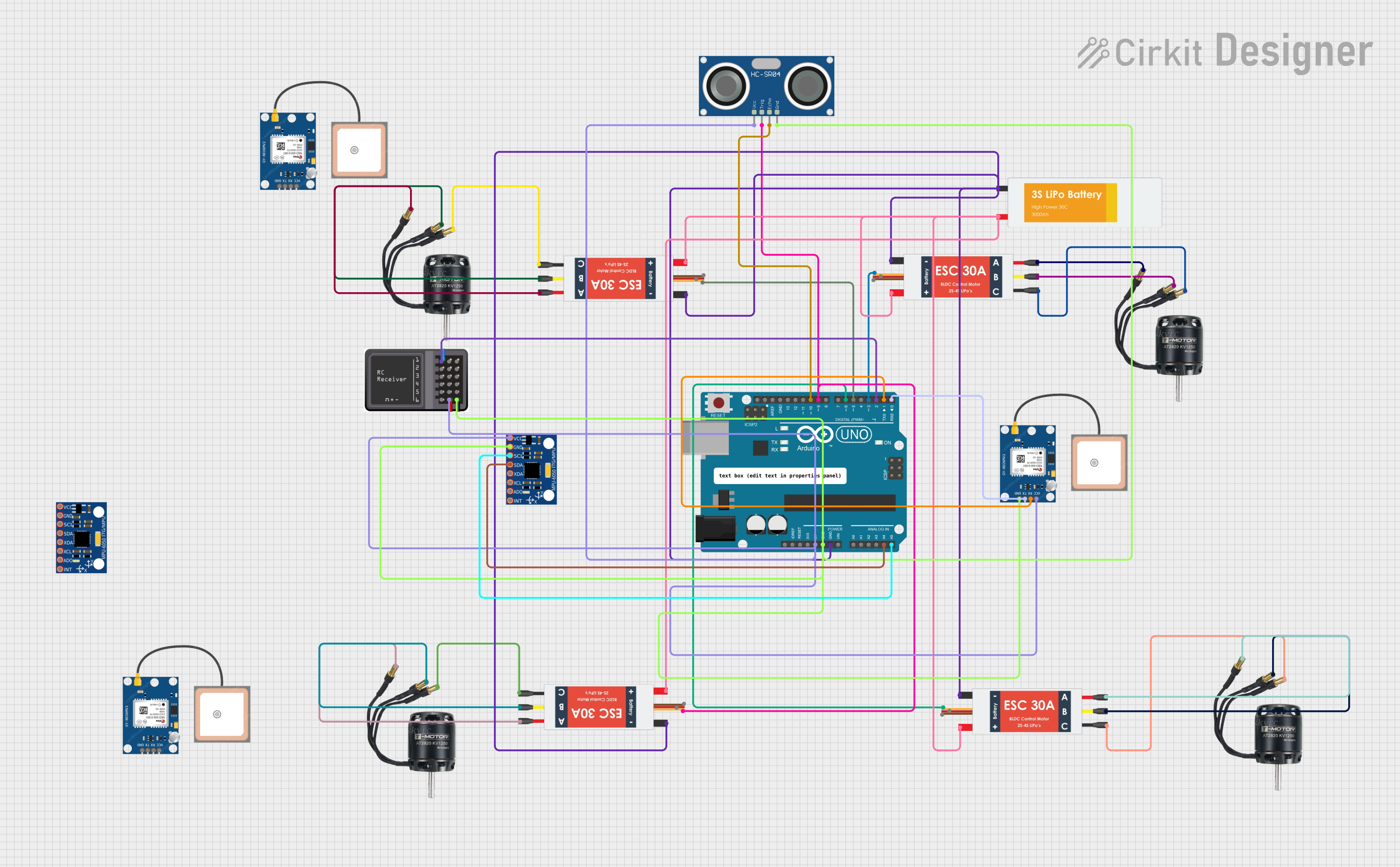
This circuit is designed to control Brushless DC (BLDC) motors using Electronic Speed Controllers (ESCs), interfaced with an Arduino UNO microcontroller. The circuit includes multiple sensors: MPU-6050 for motion tracking, HC-SR04 for distance measurement, and GPS NEO 6M modules for location tracking. A LiPo battery provides power to the system, and an RC Receiver Module is included for remote control capabilities.
Component List
Microcontroller
- Arduino UNO: A microcontroller board based on the ATmega328P. It has digital input/output pins, analog inputs, a USB connection for programming, and power management features.
Motors
- BLDC Motor: Brushless DC motors that provide high power and efficiency, commonly used in drones and RC vehicles.
Motor Controllers
- Electronic Speed Controller (ESC): Interfaces between the microcontroller and the BLDC motors to control their speed and direction.
Sensors
- MPU-6050: A motion tracking device that contains a MEMS accelerometer and a MEMS gyro in a single chip. It is used for measuring acceleration and angular rate.
- HC-SR04 Ultrasonic Sensor: Measures distance by emitting an ultrasonic wave and measuring the time taken for the echo to return.
- GPS NEO 6M: A GPS module that provides location coordinates.
Power Supply
- Lipo Battery: A rechargeable battery that provides power to the ESCs and motors.
Communication
- RC Receiver Module: Receives signals from a remote control transmitter and outputs control signals to the microcontroller.
Wiring Details
Arduino UNO
- 5V: Powers the MPU-6050, HC-SR04 Ultrasonic Sensor, GPS NEO 6M, and RC Receiver Module.
- GND: Common ground for MPU-6050, HC-SR04 Ultrasonic Sensor, GPS NEO 6M, RC Receiver Module, and ESCs.
- A4 (SDA): Data line for I2C communication with MPU-6050.
- A5 (SCL): Clock line for I2C communication with MPU-6050.
- D10: Connected to the ECHO pin of the HC-SR04 Ultrasonic Sensor.
- D9: Connected to the TRIG pin of the HC-SR04 Ultrasonic Sensor and Signal pin of one ESC.
- D6, D5, D3: Signal pins for ESCs controlling BLDC motors.
- D2: Connected to the S1 pin of the RC Receiver Module.
- D1 (TX): Transmit pin connected to the RX pin of the GPS NEO 6M.
- D0 (RX): Receive pin connected to the TX pin of the GPS NEO 6M.
BLDC Motors
- Connected to the M1, M2, and M3 pins of their respective ESCs.
Electronic Speed Controllers (ESC)
- Battery VCC: Connected to the VCC of the LiPo Battery.
- Battery GND: Common ground with the Arduino UNO and LiPo Battery.
- Signal: Receives PWM signals from the Arduino UNO to control motor speed.
GPS NEO 6M
- VCC: Powered by the 5V output from the Arduino UNO.
- RX: Receives data from the Arduino UNO's TX pin.
- TX: Transmits data to the Arduino UNO's RX pin.
- GND: Common ground with the Arduino UNO.
HC-SR04 Ultrasonic Sensor
- VCC: Powered by the 5V output from the Arduino UNO.
- TRIG: Trigger pin connected to the D9 pin of the Arduino UNO.
- ECHO: Echo pin connected to the D10 pin of the Arduino UNO.
- GND: Common ground with the Arduino UNO.
MPU-6050
- VCC: Powered by the 5V output from the Arduino UNO.
- GND: Common ground with the Arduino UNO.
- SDA: Data line connected to the A4 pin of the Arduino UNO.
- SCL: Clock line connected to the A5 pin of the Arduino UNO.
RC Receiver Module
- Vcc: Powered by the 5V output from the Arduino UNO.
- S1: Signal pin connected to the D2 pin of the Arduino UNO.
- GND: Common ground with the Arduino UNO.
Lipo Battery
- VCC: Provides power to the ESCs.
- GND: Common ground with the ESCs and Arduino UNO.
Documented Code
#include <Wire.h>
#include <MPU6050.h>
#include <TinyGPS++.h>
#include <SoftwareSerial.h>

MPU6050 mpu;
TinyGPSPlus gps;
SoftwareSerial ss(4, 3); // GPS RX, TX

void setup() {
  Serial.begin(9600);
  ss.begin(9600);

  mpu.initialize();
  pinMode(3, OUTPUT); // ESC signal pin
}

void loop() {
  // Control motors with PWM signal
  analogWrite(3, 128); // Example: Set throttle to 50%

  // Read IMU data
  int16_t ax, ay, az;
  mpu.getAcceleration(&ax, &ay, &az);

  // Read GPS data
  while (ss.available() > 0) {
    gps.encode(ss.read());
    if (gps.location.isUpdated()) {
      Serial.print("Latitude: ");
      Serial.println(gps.location.lat(), 6);
      Serial.print("Longitude: ");
      Serial.println(gps.location.lng(), 6);
    }
  }
}
The code is written for the Arduino UNO and includes libraries for the MPU6050 sensor, TinyGPS++ for the GPS module, and SoftwareSerial for communication with the GPS module. The setup() function initializes the serial communication, the MPU6050 sensor, and configures the ESC signal pin. The loop() function controls the motor speed, reads data from the MPU6050 sensor, and processes GPS data, outputting the latitude and longitude to the serial monitor.