Cirkit Designer
Your all-in-one circuit design IDE
Home /
Project Documentation
Arduino-Controlled 4-Channel Relay with DC Motors
Circuit Documentation
Summary of the Circuit
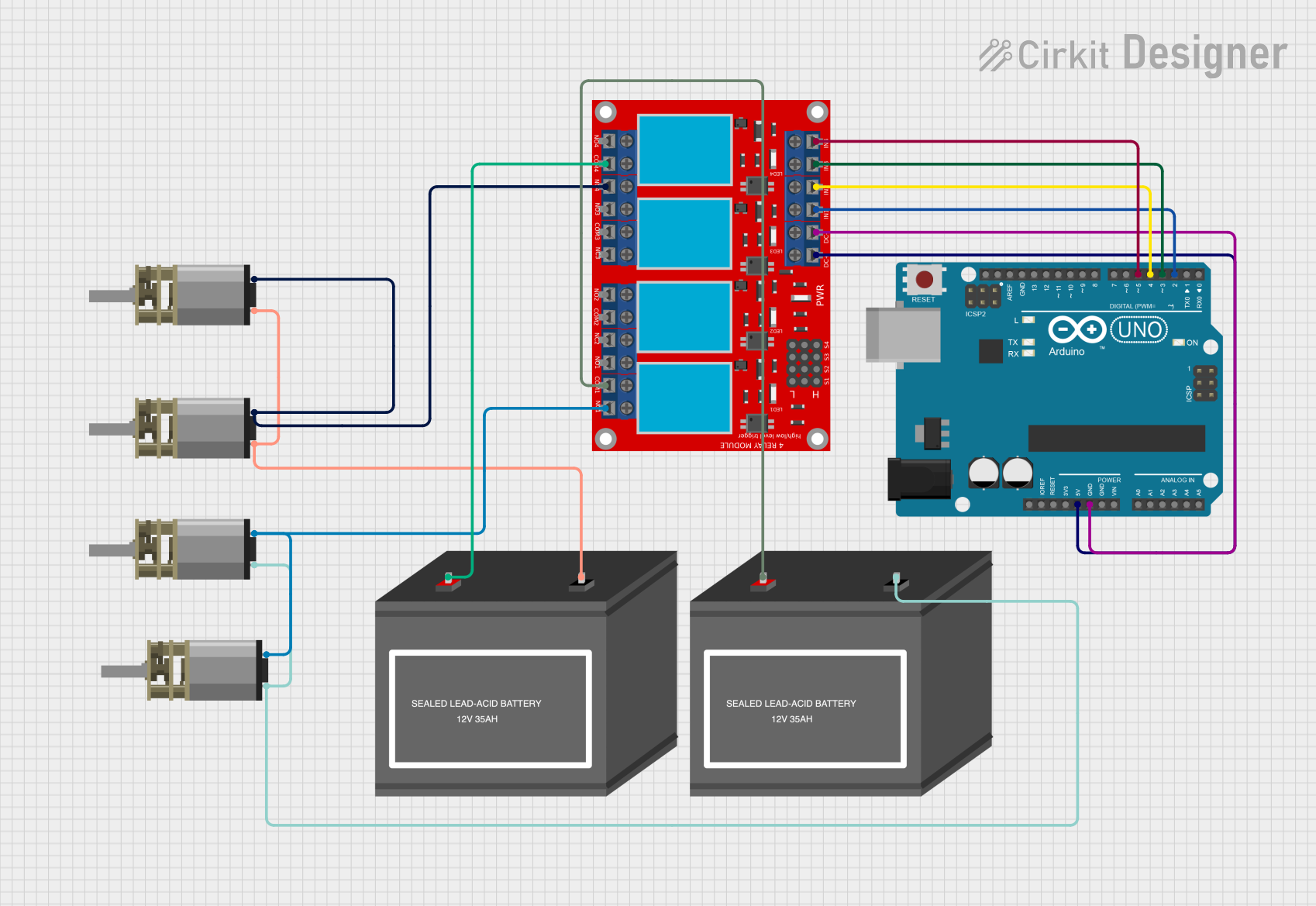
This circuit is designed to control four DC Mini Metal Gear Motors using an Arduino UNO microcontroller and a 4-channel relay module. The Arduino UNO is powered by its onboard 5V regulator and is used to control the relay module, which in turn switches the motors on and off. Two 12V mini batteries are used to power the motors through the relay module. The relay module allows for independent control of the motors, enabling the Arduino to activate or deactivate each motor as needed.
Component List
Arduino UNO
- Microcontroller board based on the ATmega328P
- It has 14 digital input/output pins, 6 analog inputs, a 16 MHz quartz crystal, a USB connection, a power jack, an ICSP header, and a reset button.
4 Channel Relay Module
- A module with 4 relays that can be individually controlled by digital outputs from the Arduino.
- Each relay has a Normally Open (N.O.), a Normally Closed (N.C.), and a Common (COM) terminal.
DC Mini Metal Gear Motor
- A compact and powerful DC motor with a gearbox for increased torque.
- It has two input terminals for controlling the direction and speed of the motor.
12V Battery (mini)
- A small 12V battery used to provide power to the DC motors through the relay module.
Wiring Details
Arduino UNO
- 5V connected to the VCC+ of the 4 channel relay module.
- GND connected to the VCC- (GND) of the 4 channel relay module.
- D2 connected to IN 1 of the 4 channel relay module.
- D3 connected to IN 3 of the 4 channel relay module.
- D4 connected to IN 2 of the 4 channel relay module.
- D5 connected to IN 4 of the 4 channel relay module.
4 Channel Relay Module
- VCC+ connected to 5V of the Arduino UNO.
- VCC- (GND) connected to GND of the Arduino UNO.
- IN 1 connected to D2 of the Arduino UNO.
- IN 2 connected to D4 of the Arduino UNO.
- IN 3 connected to D3 of the Arduino UNO.
- IN 4 connected to D5 of the Arduino UNO.
- COM 1 and COM 4 connected to the positive terminals of the 12V mini batteries.
- N.C. 1 and N.C. 4 connected to the IN2 terminals of the DC Mini Metal Gear Motors.
DC Mini Metal Gear Motor
- IN1 terminals of all motors connected to the negative terminals of the 12V mini batteries.
- IN2 terminals of two motors connected to N.C. 4 of the 4 channel relay module.
- IN2 terminals of the other two motors connected to N.C. 1 of the 4 channel relay module.
12V Battery (mini)
- + terminal of one battery connected to COM 4 of the 4 channel relay module.
- + terminal of the other battery connected to COM 1 of the 4 channel relay module.
- - terminals of both batteries connected to IN1 terminals of the DC Mini Metal Gear Motors.
Documented Code
Arduino UNO - sketch.ino
void setup() {
  // put your setup code here, to run once:

}

void loop() {
  // put your main code here, to run repeatedly:

}
Additional Notes
- The provided code is a template and does not contain any functional code to control the relay module or the motors. The user must implement the control logic within the
setup()andloop()functions. - The
setup()function is used to initialize the pins that control the relay module as output pins. - The
loop()function should contain the code to control the state of each relay, thus controlling the motors' operation.
Please note that the actual implementation of the control logic will depend on the specific requirements of the application for which this circuit is being used.