Cirkit Designer
Your all-in-one circuit design IDE
Home /
Project Documentation
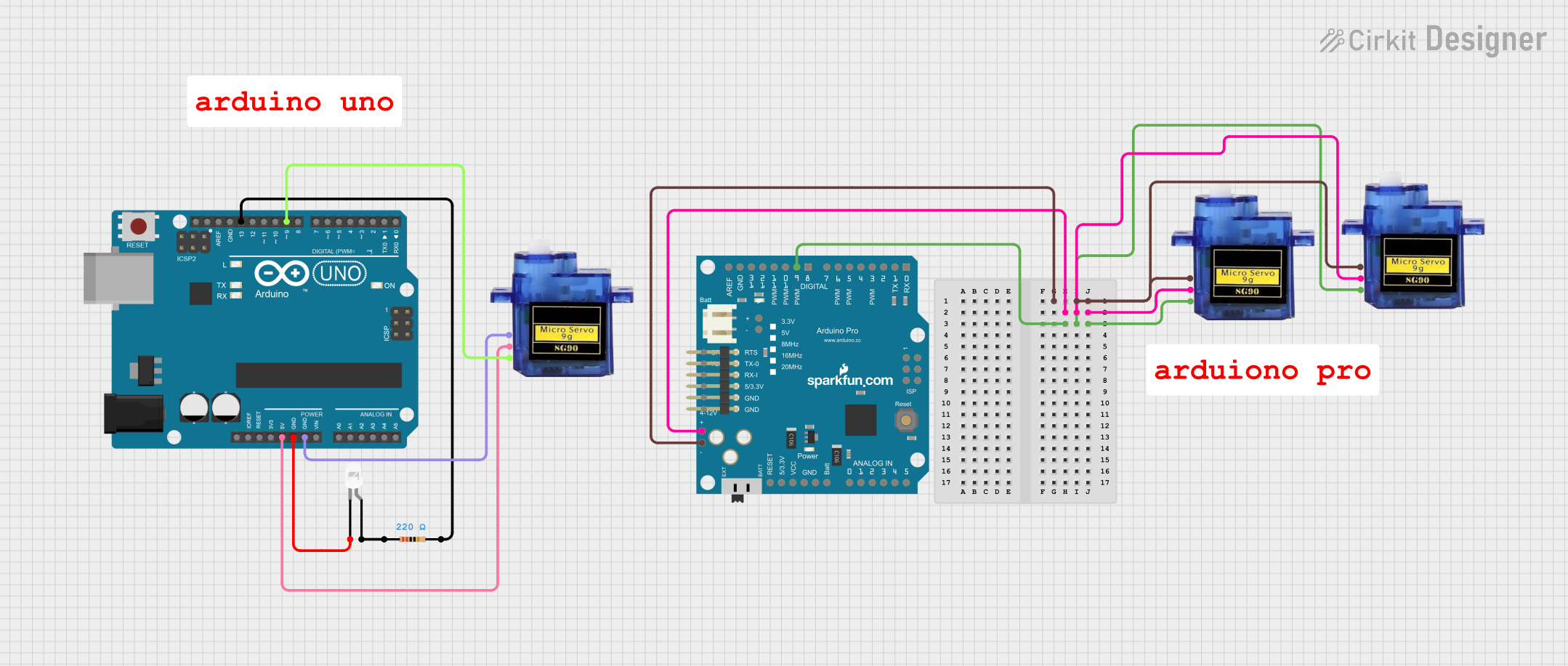
Arduino UNO and Pro Controlled Multi-Servo System with LED Indicator
Circuit Documentation
Summary
This circuit involves an Arduino UNO and an Arduino Pro microcontroller, controlling multiple components including micro servos, an LED, and a resistor. The Arduino UNO is primarily responsible for controlling a micro servo and an LED, while the Arduino Pro controls two additional micro servos. The circuit is designed to demonstrate basic control of servos and an LED using microcontrollers.
Component List
Arduino UNO
- Description: A microcontroller board based on the ATmega328P.
- Pins: UNUSED, IOREF, Reset, 3.3V, 5V, GND, Vin, A0, A1, A2, A3, A4, A5, SCL, SDA, AREF, D13, D12, D11, D10, D9, D8, D7, D6, D5, D4, D3, D2, D1, D0
Micro servo 9G (Servo 1)
- Description: A small and lightweight servo motor.
- Pins: GND, +5V, PWM
LED: Two Pin (white)
- Description: A white LED with two pins.
- Pins: cathode, anode
Resistor
- Description: A resistor with a resistance of 220 Ohms.
- Pins: pin1, pin2
- Properties:
- Resistance: 220 Ohms
Arduino Pro
- Description: A microcontroller board based on the ATmega328.
- Pins: D1/TX, D0/RX, D2, D3 PWM, D4/A6, D5 PWM, D6 PWM, D7, A0, A1, A2, A3, A4, A5, D8, D9 PWM, D10 PWM/SS, D11/MOSI, D12/MISO, D13/SCK, GND, AREF, RESET, 3V3, VCC, LIPO, MISO, SCK, MOSI, 5V, RX, TX, DTR
Micro servo 9G (Servo 2)
- Description: A small and lightweight servo motor.
- Pins: GND, +5V, PWM
Micro servo 9G (Servo 3)
- Description: A small and lightweight servo motor.
- Pins: GND, +5V, PWM
Wiring Details
Arduino UNO
- 5V connected to +5V of Micro servo 9G (Servo 1)
- GND connected to GND of Micro servo 9G (Servo 1)
- GND connected to cathode of LED: Two Pin (white)
- D13 connected to pin2 of Resistor
- D9 connected to PWM of Micro servo 9G (Servo 1)
Micro servo 9G (Servo 1)
- +5V connected to 5V of Arduino UNO
- GND connected to GND of Arduino UNO
- PWM connected to D9 of Arduino UNO
LED: Two Pin (white)
- cathode connected to GND of Arduino UNO
- anode connected to pin1 of Resistor
Resistor
- pin1 connected to anode of LED: Two Pin (white)
- pin2 connected to D13 of Arduino UNO
Arduino Pro
- D9 PWM connected to PWM of Micro servo 9G (Servo 2) and Micro servo 9G (Servo 3)
- GND connected to GND of Micro servo 9G (Servo 2) and Micro servo 9G (Servo 3)
- 5V connected to +5V of Micro servo 9G (Servo 2) and Micro servo 9G (Servo 3)
Micro servo 9G (Servo 2)
- +5V connected to 5V of Arduino Pro
- GND connected to GND of Arduino Pro
- PWM connected to D9 PWM of Arduino Pro
Micro servo 9G (Servo 3)
- +5V connected to 5V of Arduino Pro
- GND connected to GND of Arduino Pro
- PWM connected to D9 PWM of Arduino Pro
Documented Code
Arduino UNO Code
void setup() {
  // put your setup code here, to run once:

}

void loop() {
  // put your main code here, to run repeatedly:

}
Additional Documentation
This documentation provides a comprehensive overview of the circuit, including a summary, detailed component list, wiring details, and the code used for the microcontrollers.