
ESP32-Based Environmental Monitoring Station with Solar Charging
View and Edit Project In Cirkit Designer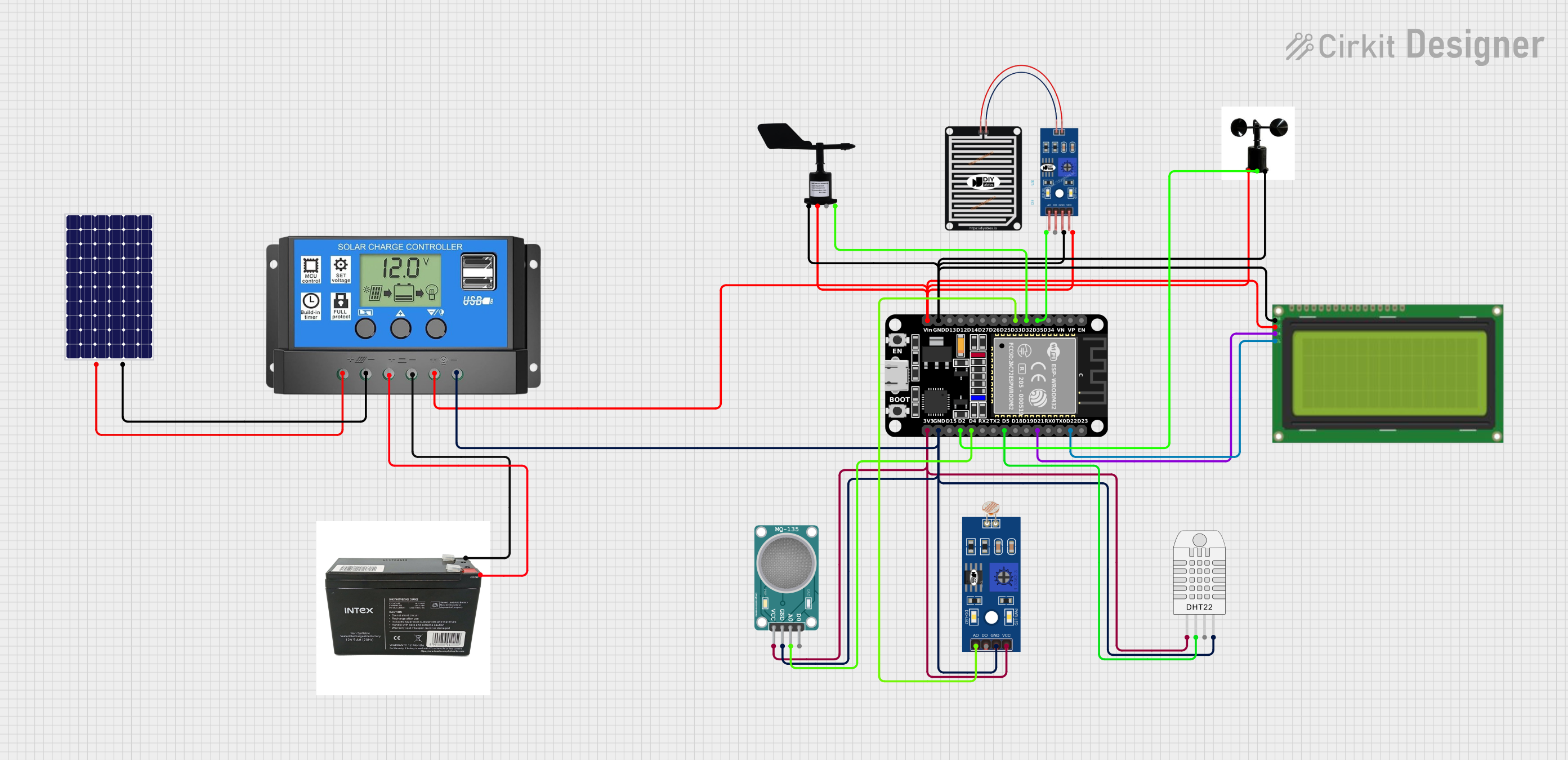
Circuit Documentation
Summary
The circuit in question is designed to interface various sensors and peripherals with an ESP32 microcontroller. The sensors include a rain sensor, an LDR (light-dependent resistor), an MQ-135 air quality sensor, a wind direction sensor, and an anemometer. Additionally, the circuit includes a 20x4 LCD with I2C interface for display purposes, a DHT22 temperature and humidity sensor, a solar charge controller, a solar panel, and a UPS battery for power management. The ESP32 serves as the central processing unit, collecting data from the sensors and managing the display.
Component List
ESP32 (30 pin)
- Microcontroller with a variety of digital and analog pins, used as the main processing unit of the circuit.
Lcd 20x4 i2c
- An alphanumeric liquid crystal display with an I2C interface, used for displaying information.
DHT22 (Wokwi Compatible)
- A sensor for measuring temperature and humidity.
LDR
- A light-dependent resistor, used for measuring light intensity.
MQ-135 SENSOR AIR QUALITY
- A sensor used for detecting a wide range of gases, including NH3, NOx, alcohol, benzene, smoke, and CO2.
RAIN SENSOR
- A sensor used for detecting rainwater.
WindDirectionSensor
- A sensor used for determining the direction of the wind.
Anemometer
- A device used for measuring wind speed.
Solar Charge Controller
- A device that controls the charging of a battery from a solar panel and provides load control.
Solar Panel
- A photovoltaic panel used for converting solar energy into electrical energy.
UPS BATTERY
- A battery used for providing uninterrupted power supply.
Wiring Details
ESP32 (30 pin)
D35connected to RAIN SENSOR AOD32connected to WindDirectionSensor DataD33connected to LDR A0GNDconnected to common groundVinconnected to Solar Charge Controller Load +D22connected to Lcd 20x4 i2c SCLD21connected to Lcd 20x4 i2c SCAD5connected to DHT22 (Wokwi Compatible) SDAD4connected to MQ-135 SENSOR AIR QUALITY A0D2connected to Anemometer signal3V3connected to common VCC
Lcd 20x4 i2c
GNDconnected to common ground5vconnected to Solar Charge Controller Load +
DHT22 (Wokwi Compatible)
SDAconnected to ESP32 (30 pin) D5GNDconnected to common groundVCCconnected to common VCC
LDR
A0connected to ESP32 (30 pin) D33GNDconnected to common groundVCCconnected to common VCC
MQ-135 SENSOR AIR QUALITY
A0connected to ESP32 (30 pin) D4GNDconnected to common groundVCCconnected to common VCC
RAIN SENSOR
AOconnected to ESP32 (30 pin) D35GRDconnected to common groundVCCconnected to Solar Charge Controller Load +
WindDirectionSensor
Dataconnected to ESP32 (30 pin) D32GNDconnected to common groundVINconnected to Solar Charge Controller Load +
Anemometer
signalconnected to ESP32 (30 pin) D2gndconnected to common groundvccconnected to Solar Charge Controller Load +
Solar Charge Controller
Solar Cell +connected to Solar Panel +Solar Cell -connected to Solar Panel -Battery +connected to UPS BATTERY VCCBattery -connected to UPS BATTERY GNDLoad +connected to common VCCLoad -connected to common ground
Solar Panel
+connected to Solar Charge Controller Solar Cell +-connected to Solar Charge Controller Solar Cell -
UPS BATTERY
GNDconnected to Solar Charge Controller Battery -VCCconnected to Solar Charge Controller Battery +
Documented Code
Anemometer Code (sketch.ino)
void setup() {
  // put your setup code here, to run once:

}

void loop() {
  // put your main code here, to run repeatedly:

}
Note: The provided code for the anemometer is a template with no specific functionality. It needs to be populated with the actual logic for reading the anemometer data and possibly transmitting it to the ESP32 for processing.
Anemometer Documentation (documentation.txt)
No code was provided for this file.
End of Documentation