
Circuit Documentation
Summary of the Circuit
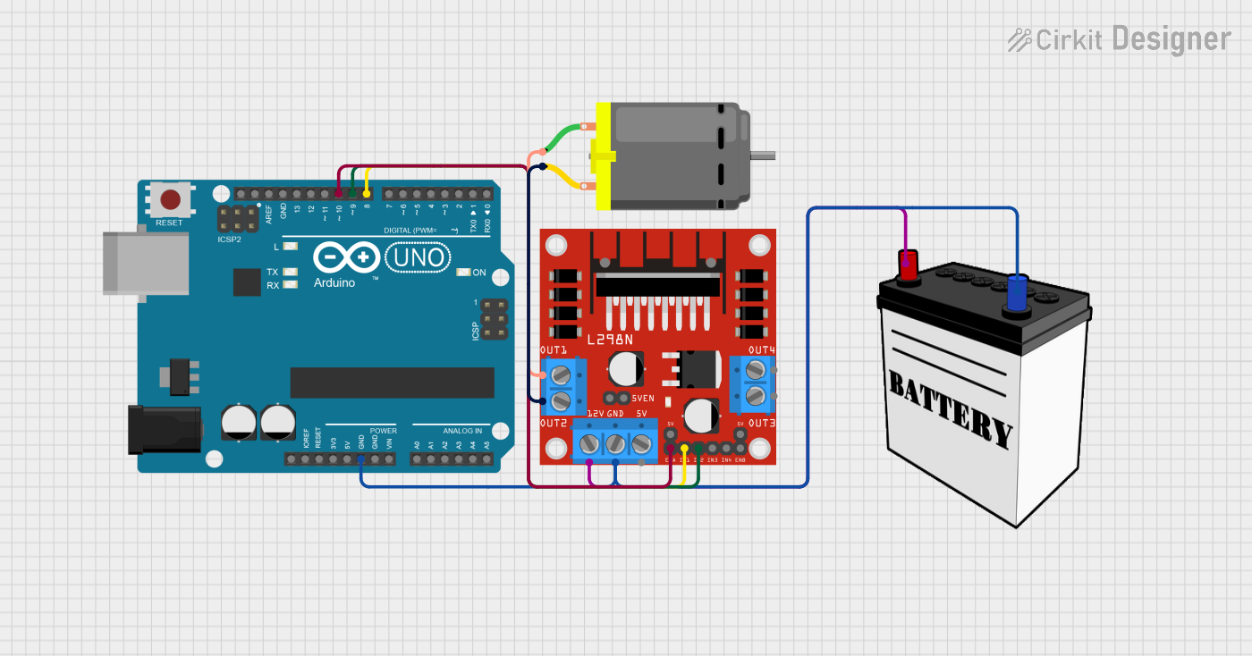
This circuit is designed to control a DC motor using an Arduino UNO microcontroller and an L298N DC motor driver. The motor's speed and direction are controlled by the Arduino, which sends signals to the L298N driver. The driver, in turn, powers the motor using a 12V battery as the power source. The Arduino's firmware is programmed to alternate the motor's rotation between clockwise and counterclockwise directions every 3 seconds.
Component List
Arduino UNO
- Description: A microcontroller board based on the ATmega328P.
- Purpose: Acts as the control unit for the motor, sending signals to the L298N driver to control the motor's speed and direction.
- Pins Used: GND, D10, D9, D8.
L298N DC Motor Driver
- Description: A high-power motor driver capable of driving up to two DC motors.
- Purpose: Receives control signals from the Arduino to drive the connected DC motor.
- Pins Used: GND, ENA, IN1, IN2, OUT1, OUT2, 12V.
12V Battery
- Description: A power source for the circuit.
- Purpose: Provides the necessary power to the L298N motor driver and the DC motor.
- Pins Used: VCC, GND.
DC Motor
- Description: An electric motor that runs on direct current (DC) electricity.
- Purpose: The actuator in the circuit that performs work when powered by the motor driver.
- Pins Used: pin 1, pin 2.
Wiring Details
Arduino UNO
- GND connected to the common ground of the circuit.
- D10 connected to ENA on the L298N motor driver to control motor speed.
- D9 connected to IN2 on the L298N motor driver to set motor direction.
- D8 connected to IN1 on the L298N motor driver to set motor direction.
L298N DC Motor Driver
- GND connected to the common ground of the circuit.
- ENA connected to D10 on the Arduino UNO for speed control.
- IN1 connected to D8 on the Arduino UNO for direction control.
- IN2 connected to D9 on the Arduino UNO for direction control.
- OUT1 connected to pin 1 on the DC Motor.
- OUT2 connected to pin 2 on the DC Motor.
- 12V connected to VCC on the 12V Battery for power.
12V Battery
- VCC connected to 12V on the L298N motor driver to supply power.
- GND connected to the common ground of the circuit.
DC Motor
- pin 1 connected to OUT1 on the L298N motor driver.
- pin 2 connected to OUT2 on the L298N motor driver.
Documented Code
// Define motor control pins
int motorPin1 = 8;  // IN1 on L298N
int motorPin2 = 9;  // IN2 on L298N
int enablePin = 10; // EN A on L298N (controls speed)

void setup() {
  // Set motor control pins as outputs
  pinMode(motorPin1, OUTPUT);
  pinMode(motorPin2, OUTPUT);
  pinMode(enablePin, OUTPUT);

  // Set initial motor speed (255 is full speed, 0 is off)
  analogWrite(enablePin, 200); // Set motor speed to 200 out of 255
}

void loop() {
  // Rotate motor forward (clockwise)
  digitalWrite(motorPin1, HIGH); // Turn on IN1
  digitalWrite(motorPin2, LOW);  // Turn off IN2
  delay(3000);  // Keep running forward for 3 seconds

  // Rotate motor backward (counter-clockwise)
  digitalWrite(motorPin1, LOW);  // Turn off IN1
  digitalWrite(motorPin2, HIGH); // Turn on IN2
  delay(3000);  // Keep running backward for 3 seconds
}
Filename: sketch.ino
Description: This Arduino sketch sets up the motor control pins and initializes the motor speed. In the main loop, it alternates the motor's direction every 3 seconds by toggling the IN1 and IN2 pins of the L298N motor driver.