
Arduino-Controlled Robotics Platform with Reflectance Sensor Array and Ultrasonic Obstacle Detection
View and Edit Project In Cirkit Designer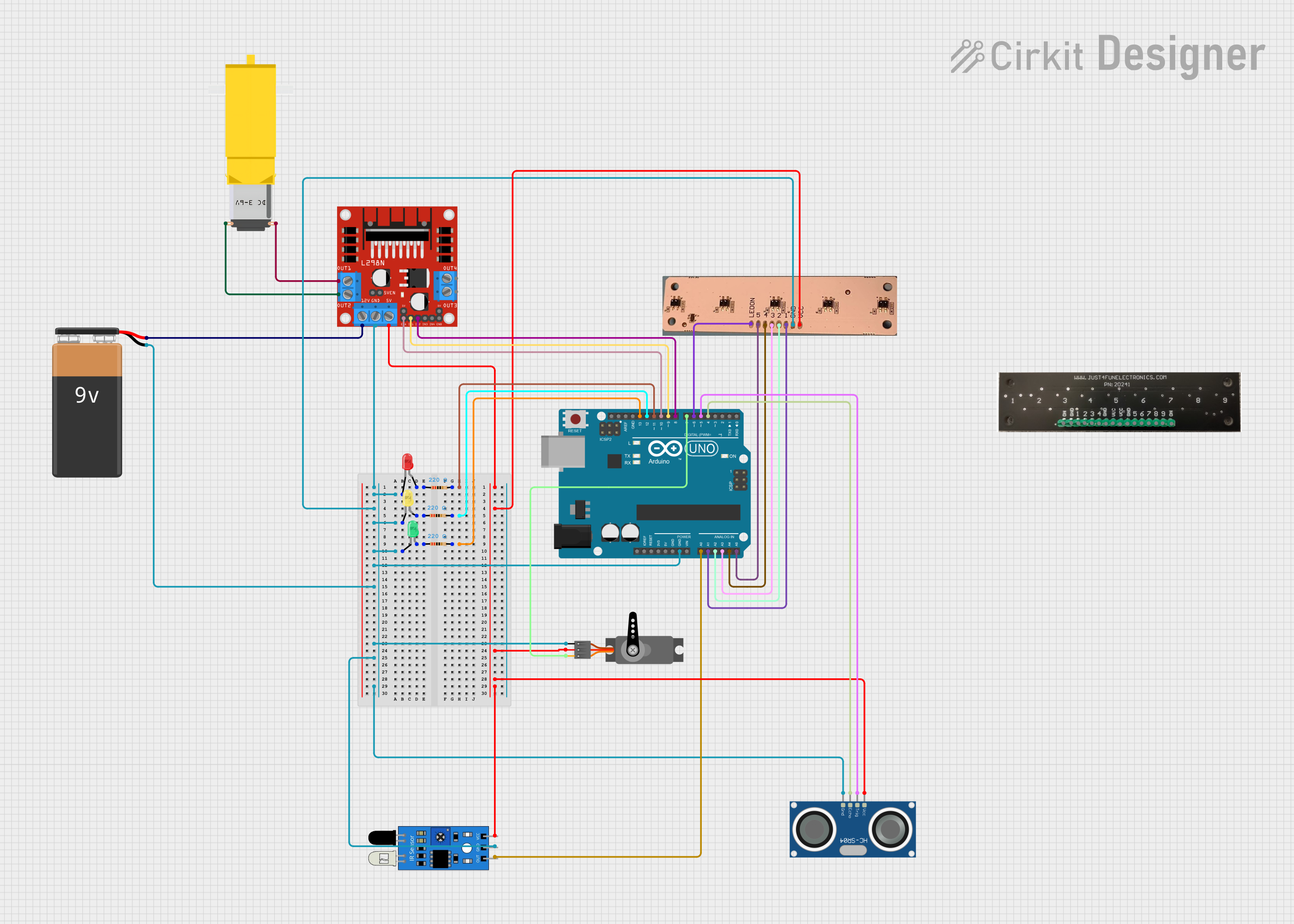
Circuit Documentation
Summary
This document provides a detailed overview of a circuit designed to interface various sensors, actuators, and LEDs with an Arduino UNO microcontroller. The circuit includes a motor driver for controlling a DC gearmotor, a servo motor, an ultrasonic sensor, IR sensor, reflectance sensor arrays, and multiple LEDs with current-limiting resistors. A 9V battery powers the circuit, and the Arduino UNO is used to control and interface with all components.
Component List
Reflectance Sensor Array (5 pin)
- Description: A sensor array used to detect reflectance with 5 sensing elements.
- Pins: LEDON, 5, 4, 3, 2, 1, GND, VCC
Reflectance Sensor Array (9 pin)
- Description: A sensor array with 9 sensing elements for detecting reflectance.
- Pins: ON, GND, 1, 2, 3, 4, VCC, 5, 6, 7, 8, 9
9V Battery
- Description: Provides power to the circuit.
- Pins: -, +
L298N DC Motor Driver
- Description: A module for controlling DC motors.
- Pins: OUT1, OUT2, 12V, GND, 5V, OUT3, OUT4, 5V-ENA-JMP-I, 5V-ENA-JMP-O, +5V-J1, +5V-J2, ENA, IN1, IN2, IN3, IN4, ENB
Gearmotor DC / Motorreductor
- Description: A DC gearmotor for providing mechanical motion.
- Pins: Pin1, Pin2
Servo
- Description: A servo motor for precise angular positioning.
- Pins: GND, VCC, PWM
HC-SR04 Ultrasonic Sensor
- Description: An ultrasonic sensor for distance measurement.
- Pins: VCC, TRIG, ECHO, GND
LED: Two Pin (red, green, yellow)
- Description: Light Emitting Diodes of different colors for indication.
- Pins: cathode, anode
Arduino UNO
- Description: A microcontroller board based on the ATmega328P.
- Pins: UNUSED, IOREF, Reset, 3.3V, 5V, GND, Vin, A0-A5, SCL, SDA, AREF, D0-D13
Resistor (220 Ohms)
- Description: Current-limiting resistors for LEDs.
- Pins: pin1, pin2
IR Sensor
- Description: An infrared sensor for detecting proximity or object presence.
- Pins: out, gnd, vcc
Wiring Details
Reflectance Sensor Array (5 pin)
- LEDON: Connected to Arduino UNO D6
- 5: Connected to Arduino UNO A5
- 4: Connected to Arduino UNO A4
- 3: Connected to Arduino UNO A3
- 2: Connected to Arduino UNO A2
- 1: Connected to Arduino UNO A1
- GND: Connected to common ground
- VCC: Connected to L298N DC motor driver 5V
Reflectance Sensor Array (9 pin)
- Not connected in the current configuration.
9V Battery
- -: Connected to common ground
- +: Connected to L298N DC motor driver 12V
L298N DC Motor Driver
- OUT1: Connected to Gearmotor DC Pin2
- OUT2: Connected to Gearmotor DC Pin1
- 12V: Connected to 9V Battery +
- GND: Connected to common ground
- 5V: Power supply for other components
- ENA: Connected to Arduino UNO D10
- IN1: Connected to Arduino UNO D9
- IN2: Connected to Arduino UNO D8
Gearmotor DC / Motorreductor
- Pin1: Connected to L298N DC motor driver OUT2
- Pin2: Connected to L298N DC motor driver OUT1
Servo
- GND: Connected to common ground
- VCC: Connected to L298N DC motor driver 5V
- PWM: Connected to Arduino UNO D7
HC-SR04 Ultrasonic Sensor
- VCC: Connected to L298N DC motor driver 5V
- TRIG: Connected to Arduino UNO D5
- ECHO: Connected to Arduino UNO D4
- GND: Connected to common ground
LED: Two Pin (red, green, yellow)
- Red LED cathode: Connected to common ground, anode: Connected to Resistor (220 Ohms) pin1
- Green LED cathode: Connected to common ground, anode: Connected to Resistor (220 Ohms) pin1
- Yellow LED cathode: Connected to common ground, anode: Connected to Resistor (220 Ohms) pin1
Arduino UNO
- D11: Connected to Resistor (220 Ohms) pin2 (Red LED)
- D12: Connected to Resistor (220 Ohms) pin2 (Green LED)
- D13: Connected to Resistor (220 Ohms) pin2 (Yellow LED)
- GND: Connected to common ground
- A0: Connected to IR Sensor out
- A1-A5: Connected to Reflectance Sensor Array (5 pin) pins 1-5
- D10: Connected to L298N DC motor driver ENA
- D9: Connected to L298N DC motor driver IN1
- D8: Connected to L298N DC motor driver IN2
- D7: Connected to Servo PWM
- D6: Connected to Reflectance Sensor Array (5 pin) LEDON
- D5: Connected to HC-SR04 Ultrasonic Sensor TRIG
- D4: Connected to HC-SR04 Ultrasonic Sensor ECHO
Resistor (220 Ohms)
- Red LED: pin1 connected to LED anode, pin2 connected to Arduino UNO D11
- Green LED: pin1 connected to LED anode, pin2 connected to Arduino UNO D12
- Yellow LED: pin1 connected to LED anode, pin2 connected to Arduino UNO D13
IR Sensor
- out: Connected to Arduino UNO A0
- gnd: Connected to common ground
- vcc: Connected to L298N DC motor driver 5V
Documented Code
Arduino UNO Code (sketch.ino)
void setup() {
  // put your setup code here, to run once:

}

void loop() {
  // put your main code here, to run repeatedly:

}
Additional Notes
- The code provided is a template and does not contain any functional code to control the circuit components.
- The user must implement the setup and loop functions to initialize the pins and define the behavior of the circuit.
- The IR sensor, ultrasonic sensor, motor driver, and LEDs are interfaced with the Arduino UNO and can be controlled via the corresponding pins as detailed in the wiring section.