
Arduino-Controlled Linear Actuator with LCD Feedback and Hall Sensor Monitoring
View and Edit Project In Cirkit Designer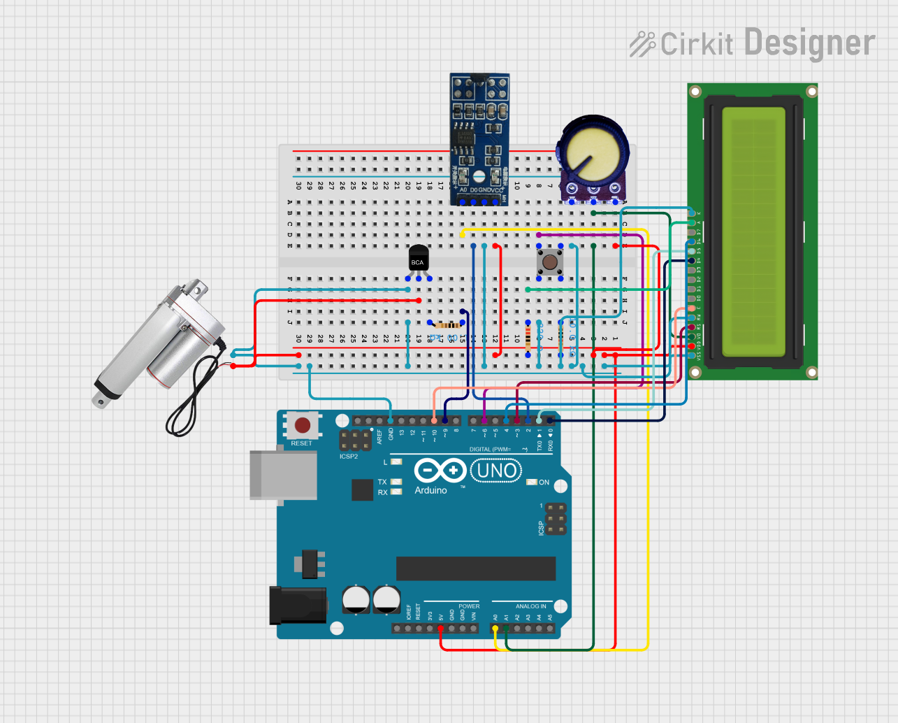
Circuit Documentation
Summary
This circuit is designed around an Arduino UNO microcontroller and includes various components such as a linear actuator, NPN-transistor, resistors, a pushbutton, a Hall sensor, an LCD display, and a potentiometer. The circuit appears to be a control system, possibly for position or speed regulation, given the presence of the actuator and sensor. The LCD display suggests that there is a user interface for feedback or control settings. The potentiometer may be used for setting a reference value or adjusting contrast on the LCD.
Component List
Arduino UNO
- Microcontroller board based on the ATmega328P
- Provides digital and analog I/O pins
- Powers the circuit and controls the components
Linear Actuator
- An electromechanical device used for motion control
- Operated by signals from the Arduino UNO
NPN-Transistor
- A type of bipolar junction transistor
- Acts as a switch or amplifier in the circuit
Resistors
- Three resistors with different resistance values:
- 1 kOhm
- 10 kOhm
- 220 Ohm
- Used for current limiting and voltage division
Pushbutton
- A momentary switch
- Used to trigger events or actions in the circuit
Hall Sensor (Magnetic)
- Senses magnetic fields
- Provides both digital and analog outputs
LCD Display 16x2
- A 16-character by 2-line liquid crystal display
- Used for displaying information to the user
Potentiometer
- A three-terminal resistor with an adjustable voltage divider
- Used for adjusting LCD contrast or as an input device
Wiring Details
Arduino UNO
5Vpin connected to the VCC of various components for powerGNDpin connected to the ground of various componentsA0pin connected to the analog output of the Hall sensorA1pin connected to the output of the potentiometerD0-D10pins connected to various pins of the LCD display for control and dataD6pin connected to one terminal of the pushbuttonD9pin connected to a 1 kOhm resistor
Linear Actuator
+terminal connected to the collector of the NPN-transistor-terminal connected to ground
NPN-Transistor
E(Emitter) connected to groundC(Collector) connected to the positive terminal of the linear actuatorB(Base) connected to a 1 kOhm resistor
Resistors
- 1 kOhm resistor connected between the base of the NPN-transistor and the
D9pin of the Arduino UNO - 10 kOhm resistor connected to the ground and the other terminal of the pushbutton
- 220 Ohm resistor connected between the
LEDApin of the LCD display and ground
Pushbutton
- One terminal connected to the
D6pin of the Arduino UNO - The other terminal connected to a 10 kOhm resistor and ground
Hall Sensor (Magnetic)
VCC (5V)connected to the 5V supply from the Arduino UNOGNDconnected to groundD0 (Digital)connected to theD2pin of the Arduino UNOA0 (Analog)connected to theA0pin of the Arduino UNO
LCD Display 16x2
VDDconnected to the 5V supply from the Arduino UNOVSS,RW, andLEDKconnected to groundLEDAconnected to a 220 Ohm resistor and groundDB4-DB7connected toD0-D4pins of the Arduino UNO for dataRSconnected to theD3pin of the Arduino UNOEconnected to theD10pin of the Arduino UNO
Potentiometer
VCCconnected to the 5V supply from the Arduino UNOOutputconnected to theA1pin of the Arduino UNOGNDconnected to ground
Documented Code
void setup() {
  // put your setup code here, to run once:

}

void loop() {
  // put your main code here, to run repeatedly:

}
The provided code is a template with empty setup() and loop() functions, which are the entry points for Arduino sketches. The setup() function is called once when the sketch starts and is used for initializing settings, while the loop() function runs repeatedly, allowing the microcontroller to perform operations based on the circuit's design and logic. Actual implementation details need to be filled in based on the specific requirements of the circuit's operation.