ESP32-Based Smart Security System with RFID and Camera
Circuit Documentation
Summary
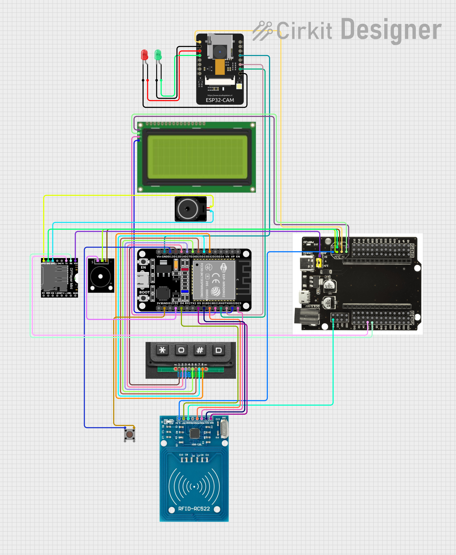
This circuit integrates various components including an ESP32 microcontroller, an LCD display with I2C interface, an RFID-RC522 module, passive buzzers, LEDs, a pushbutton, a DFPlayer MINI module, a loudspeaker, and a 4x4 keypad matrix. The ESP32 serves as the central processing unit, interfacing with input devices like the keypad and RFID reader, and output devices such as the LCD, LEDs, buzzer, and loudspeaker. The circuit is designed to perform tasks that involve user input, data display, and audio-visual feedback.
Component List
Lcd 20x4 i2c
- Description: A 20x4 character LCD display with an I2C interface for displaying text.
- Pins: GND, 5v, SCA, SCL
RFID-RC522
- Description: An RFID reader/writer module for contactless communication using radio frequency.
- Pins: VCC (3.3V), RST, GND, IRQ, MISO, MOSI, SCK, SDA
Elegoo Passive Buzzer
- Description: A passive buzzer for generating simple tones and beeps.
- Pins: GND, VCC, OUTPUT
LED: Two Pin (red)
- Description: A red LED for indicating status or alerts.
- Pins: cathode, anode
LED: Two Pin (green)
- Description: A green LED for indicating status or alerts.
- Pins: cathode, anode
Pushbutton
- Description: A standard pushbutton for user input.
- Pins: Pin 3 (out), Pin 4 (out), Pin 1 (in), Pin 2 (in)
ESP32 (30 pin)
- Description: A powerful microcontroller with Wi-Fi and Bluetooth capabilities.
- Pins: EN, VP, VN, D34, D35, D32, D33, D25, D26, D27, D14, D12, D13, GND, Vin, D23, D22, TX0, RX0, D21, D19, D18, D5, TX2, RX2, D4, D2, D15, 3V3
Loudspeaker
- Description: A speaker for playing audio.
- Pins: pin1, pin2
DFPlayer MINI
- Description: A small and low-cost MP3 module that can directly play MP3 files.
- Pins: VCC, BUSY, RX, USB -, TX, USB +, DAC_R, K2/ADC_KEY, DAC_L, K1/ADC_KEY, SPK1, IO 2, GND, SPK2, IO 1
Keypad 4x4 Matrix
- Description: A 4x4 matrix keypad for user input.
- Pins: C1, C2, C3, C4, R1, R2, R3, R4
BaseBoard ESP32-30pin
- Description: A breakout board for the ESP32, providing easy access to its pins.
- Pins: 5V, GND, 3.3V, D22, D21, VCC, D23, TX0, RX0, D19, D18, D5, D17, D16, D4, D2, D15, EN, VP, VN, D34, D35, D32, D33, D25, D26, D27, D14, D12, D13
ESP32 - CAM
- Description: An ESP32-based module with a camera and additional I/O pins.
- Pins: 5V, GND, IO12, IO13, IO15, IO14, IO2, IO4, VOT, VOR, VCC, IO0, IO16, 3V3
Wiring Details
Lcd 20x4 i2c
- GND to BaseBoard ESP32-30pin GND
- 5v to BaseBoard ESP32-30pin 5V
- SCA to ESP32 (30 pin) D21
- SCL to ESP32 (30 pin) D22
RFID-RC522
- VCC (3.3V) to BaseBoard ESP32-30pin 3.3V
- RST to ESP32 (30 pin) D4
- GND to BaseBoard ESP32-30pin GND
- IRQ (Not connected)
- MISO to ESP32 (30 pin) D19
- MOSI to ESP32 (30 pin) D23
- SCK to ESP32 (30 pin) D18
- SDA to ESP32 (30 pin) D5
Elegoo Passive Buzzer
- GND to BaseBoard ESP32-30pin GND
- VCC to BaseBoard ESP32-30pin 3.3V
- OUTPUT to ESP32 (30 pin) D2
LED: Two Pin (red)
- cathode to ESP32 - CAM GND
- anode to ESP32 - CAM IO12
LED: Two Pin (green)
- cathode to ESP32 - CAM GND
- anode to ESP32 - CAM IO13
Pushbutton
- Pin 1 (in) to ESP32 (30 pin) D13
- Pin 3 (out) to ESP32 (30 pin) GND
- Pin 2 (in), Pin 4 (out) (Not connected)
ESP32 (30 pin)
- D32 to Keypad 4x4 Matrix R4
- D33 to Keypad 4x4 Matrix R3
- D25 to Keypad 4x4 Matrix R2
- D26 to Keypad 4x4 Matrix R1
- D27 to Keypad 4x4 Matrix C3
- D14 to Keypad 4x4 Matrix C2
- D12 to Keypad 4x4 Matrix C1
- D13 to Pushbutton Pin 1 (in)
- GND to ESP32 - CAM GND, Pushbutton Pin 3 (out), Elegoo Passive Buzzer GND
- D23 to RFID-RC522 MOSI
- D22 to Lcd 20x4 i2c SCL
- TX0 to ESP32 - CAM VOR
- RX0 to ESP32 - CAM VOT
- D21 to Lcd 20x4 i2c SCA
- D19 to RFID-RC522 MISO
- D18 to RFID-RC522 SCK
- D5 to RFID-RC522 SDA
- D4 to RFID-RC522 RST
- D2 to Elegoo Passive Buzzer OUTPUT
Loudspeaker
- pin1 to DFPlayer MINI SPK1
- pin2 to DFPlayer MINI SPK2
DFPlayer MINI
- VCC to BaseBoard ESP32-30pin 5V
- RX to BaseBoard ESP32-30pin D17
- TX to BaseBoard ESP32-30pin D16
- GND to BaseBoard ESP32-30pin GND
- SPK1 to Loudspeaker pin1
- SPK2 to Loudspeaker pin2
Keypad 4x4 Matrix
- R4 to ESP32 (30 pin) D32
- R3 to ESP32 (30 pin) D33
- R2 to ESP32 (30 pin) D25
- R1 to ESP32 (30 pin) D26
- C3 to ESP32 (30 pin) D27
- C2 to ESP32 (30 pin) D14
- C1 to ESP32 (30 pin) D12
BaseBoard ESP32-30pin
- 5V to Lcd 20x4 i2c 5v, ESP32 - CAM 5V, DFPlayer MINI VCC
- GND to Lcd 20x4 i2c GND, RFID-RC522 GND, Elegoo Passive Buzzer GND, DFPlayer MINI GND
- 3.3V to RFID-RC522 VCC (3.3V), Elegoo Passive Buzzer VCC
- D22 to DFPlayer MINI RX
- D21 to DFPlayer MINI TX
ESP32 - CAM
- 5V to BaseBoard ESP32-30pin 5V
- GND to ESP32 (30 pin) GND, LED: Two Pin (green) cathode, LED: Two Pin (red) cathode
- IO12 to LED: Two Pin (red) anode
- IO13 to LED: Two Pin (green) anode
- VOR to ESP32 (30 pin) TX0
- VOT to ESP32 (30 pin) RX0
Documented Code
No code has been provided for the microcontrollers in the circuit. Please ensure to develop and document the embedded code required for the ESP32 and any other programmable components to fulfill the intended functionality of the circuit.