Cirkit Designer
Your all-in-one circuit design IDE
Home /
Project Documentation
Arduino UNO Light Sensor with KY-018 LDR for Ambient Light Detection
Circuit Documentation
Summary
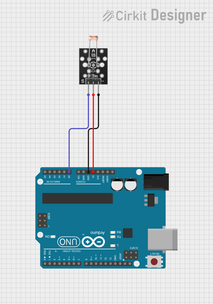
This circuit consists of an Arduino UNO microcontroller and a KY-018 LDR Photo Resistor. The Arduino UNO is used to read the analog signal from the photoresistor, which varies with the intensity of light. The circuit is powered by the 5V output from the Arduino UNO.
Component List
Arduino UNO
- Description: A microcontroller board based on the ATmega328P.
- Pins: UNUSED, IOREF, Reset, 3.3V, 5V, GND, Vin, A0, A1, A2, A3, A4, A5, SCL, SDA, AREF, D13, D12, D11, D10, D9, D8, D7, D6, D5, D4, D3, D2, D1, D0
- Purpose in Circuit: Acts as the main controller, reading the analog signal from the photoresistor and processing it.
KY-018 LDR Photo Resistor
- Description: A light-dependent resistor that changes its resistance based on the light intensity.
- Pins: Signal, VCC, Ground
- Purpose in Circuit: Provides an analog signal proportional to the light intensity to the Arduino UNO.
Wiring Details
Arduino UNO
- 5V: Connected to VCC of the KY-018 LDR Photo Resistor.
- GND: Connected to Ground of the KY-018 LDR Photo Resistor.
- A0: Connected to Signal of the KY-018 LDR Photo Resistor.
KY-018 LDR Photo Resistor
- VCC: Connected to 5V of the Arduino UNO.
- Ground: Connected to GND of the Arduino UNO.
- Signal: Connected to A0 of the Arduino UNO.
Code Documentation
Arduino UNO Code
sketch.ino
void setup() {
  // put your setup code here, to run once:

}

void loop() {
  // put your main code here, to run repeatedly:

}
documentation.txt
This code initializes the Arduino UNO but does not yet include any specific functionality. The setup() function is called once when the program starts, and the loop() function runs continuously. Future code can be added to read the analog signal from the KY-018 LDR Photo Resistor and process it accordingly.