Cirkit Designer
Your all-in-one circuit design IDE
Home /
Project Documentation
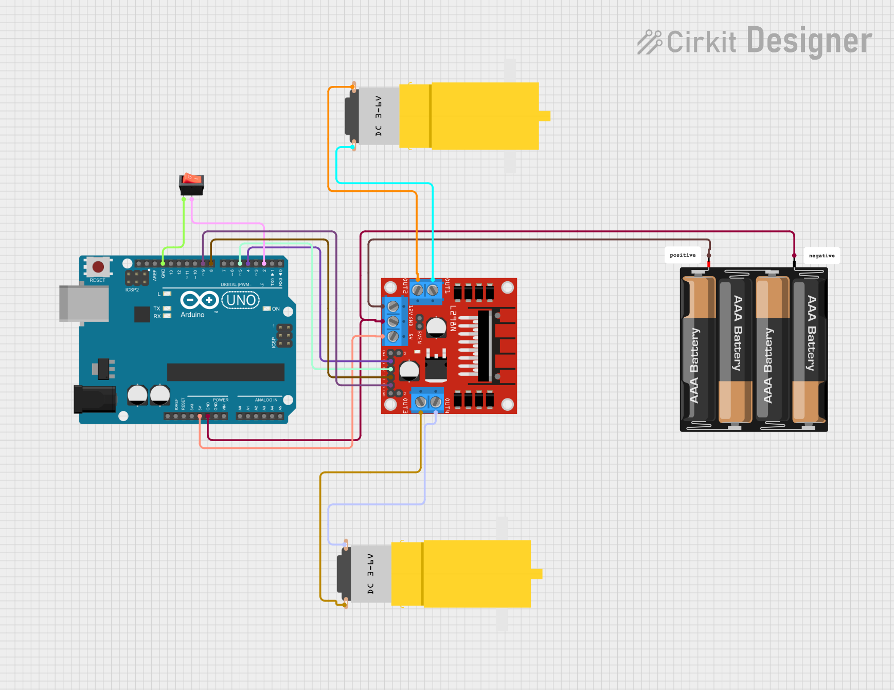
Arduino UNO Battery-Powered Motor Controller with Rocker Switch
Circuit Documentation
Summary
This document provides a detailed overview of a circuit that includes an Arduino UNO microcontroller, a rocker switch, two hobby motors, an L298N DC motor driver, and a 4 x AAA battery mount. The circuit is designed to control the motors using the Arduino UNO, with power supplied by the battery mount and motor driver.
Component List
Arduino UNO
- Description: A microcontroller board based on the ATmega328P.
- Pins: UNUSED, IOREF, Reset, 3.3V, 5V, GND, Vin, A0, A1, A2, A3, A4, A5, SCL, SDA, AREF, D13, D12, D11, D10, D9, D8, D7, D6, D5, D4, D3, D2, D1, D0
Rocker Switch
- Description: A simple on/off switch.
- Pins: output, input
Motor amarillo motorreductor hobby (Motor 1)
- Description: A small DC motor with a gearbox.
- Pins: vcc, GND
Motor amarillo motorreductor hobby (Motor 2)
- Description: A small DC motor with a gearbox.
- Pins: vcc, GND
L298N DC Motor Driver
- Description: A dual H-Bridge motor driver.
- Pins: OUT1, OUT2, 12V, GND, 5V, OUT3, OUT4, 5V-ENA-JMP-I, 5V-ENA-JMP-O, +5V-J1, +5V-J2, ENA, IN1, IN2, IN3, IN4, ENB
4 x AAA Battery Mount
- Description: A battery holder for four AAA batteries.
- Pins: -, +
Wiring Details
Arduino UNO
- 5V connected to 5V of L298N DC motor driver.
- GND connected to GND of L298N DC motor driver, GND of 4 x AAA Battery Mount, and input of rocker switch.
- D9 connected to IN4 of L298N DC motor driver.
- D8 connected to IN3 of L298N DC motor driver.
- D5 connected to IN2 of L298N DC motor driver.
- D4 connected to IN1 of L298N DC motor driver.
- D2 connected to output of rocker switch.
Rocker Switch
- input connected to GND of Arduino UNO.
- output connected to D2 of Arduino UNO.
Motor amarillo motorreductor hobby (Motor 1)
- GND connected to OUT1 of L298N DC motor driver.
- vcc connected to OUT2 of L298N DC motor driver.
Motor amarillo motorreductor hobby (Motor 2)
- GND connected to OUT3 of L298N DC motor driver.
- vcc connected to OUT4 of L298N DC motor driver.
L298N DC Motor Driver
- 5V connected to 5V of Arduino UNO.
- GND connected to GND of Arduino UNO and - of 4 x AAA Battery Mount.
- 12V connected to + of 4 x AAA Battery Mount.
- IN4 connected to D9 of Arduino UNO.
- IN3 connected to D8 of Arduino UNO.
- IN2 connected to D5 of Arduino UNO.
- IN1 connected to D4 of Arduino UNO.
- OUT1 connected to GND of Motor 1.
- OUT2 connected to vcc of Motor 1.
- OUT3 connected to GND of Motor 2.
- OUT4 connected to vcc of Motor 2.
4 x AAA Battery Mount
- - connected to GND of L298N DC motor driver and GND of Arduino UNO.
- + connected to 12V of L298N DC motor driver.
Documented Code
Arduino UNO Code (sketch.ino)
void setup() {
  // put your setup code here, to run once:

}

void loop() {
  // put your main code here, to run repeatedly:

}
Documentation (documentation.txt)
This document provides a comprehensive overview of the circuit, including the components used, their wiring details, and the code for the Arduino UNO microcontroller.