
Arduino and Raspberry Pi-Based Soil Monitoring System with LoRa and RS485 Communication
View and Edit Project In Cirkit Designer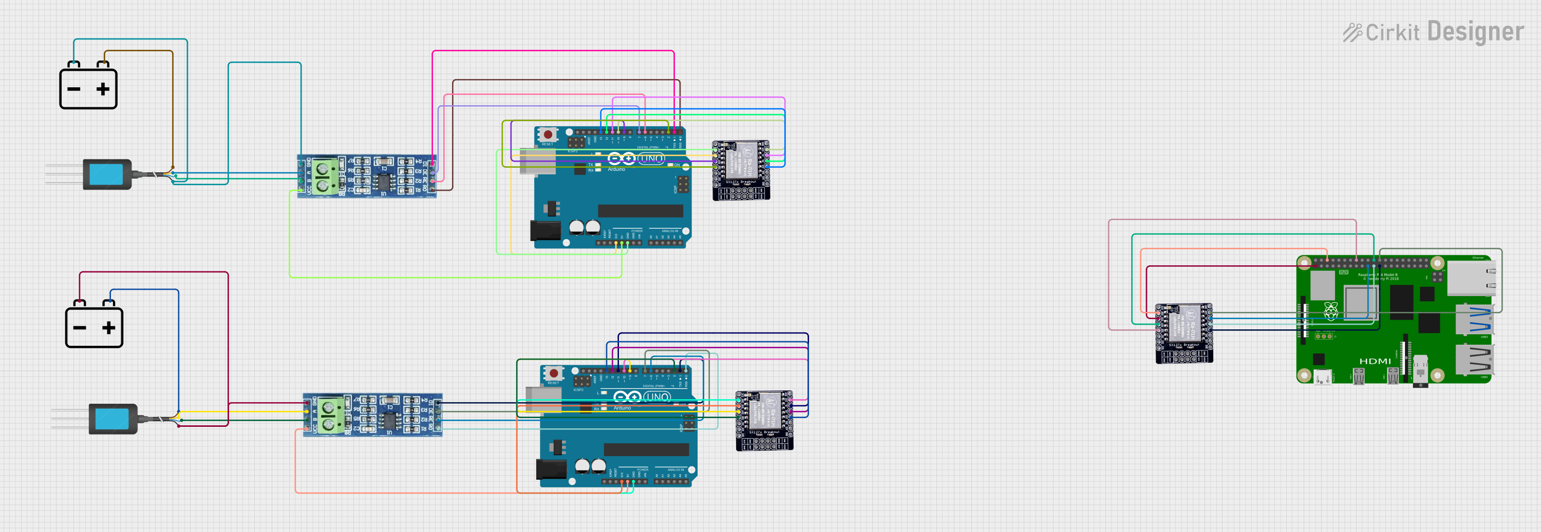
Circuit Documentation
Summary
This circuit involves multiple components including Arduino UNOs, NPK Soil Sensors, RS485 modules, LORA modules, and a Raspberry Pi 4B. The circuit is designed to interface soil sensors with microcontrollers and communicate data wirelessly using LORA modules. The RS485 modules are used for serial communication between the soil sensors and the microcontrollers.
Component List
Arduino UNO
- Description: A microcontroller board based on the ATmega328P.
- Pins: UNUSED, IOREF, Reset, 3.3V, 5V, GND, Vin, A0, A1, A2, A3, A4, A5, SCL, SDA, AREF, D13, D12, D11, D10, D9, D8, D7, D6, D5, D4, D3, D2, D1, D0
NPK Soil Sensor
- Description: A sensor used to measure the nitrogen, phosphorus, and potassium levels in soil.
- Pins: 12V DC, A, B, GND
RS485
- Description: A module used for serial communication over long distances.
- Pins: VCC, RO, RE, GND, B, A, DE, DI
12V Battery
- Description: A power source providing 12V DC.
- Pins: -, +
LORA_01H
- Description: A module used for long-range wireless communication.
- Pins: A/G, GND, 3V3, RST, IO_0, IO_1, IO_2, IO-3, NSS, MOSI, MISO, SCK, IO_5, IO_4
Raspberry Pi 4B
- Description: A single-board computer used for various applications.
- Pins: 3V3, 5V, GPIO2, GPIO3, GND, GPIO4, GPIO14, GPIO15, GPIO17, GPIO18, GPIO27, GPIO22, GPIO23, GPIO24, GPIO10, GPIO9, GPIO25, GPIO11, GPIO8, GPIO7, ID_SD, GPIO5, GPIO6, GPIO12, GPIO13, GPIO19, GPIO16, GPIO26, GPIO20, GPIO21, ID_SC, TR01_TAP, TR00_TAP, TR03_TAP, TR02_TAP, RUN, GLOBAL_EN
Wiring Details
Arduino UNO
- 3.3V connected to LORA_01H 3V3
- 5V connected to RS485 VCC
- GND connected to LORA_01H GND
- D13 connected to LORA_01H SCK
- D12 connected to LORA_01H MISO
- D11 connected to LORA_01H MOSI
- D10 connected to LORA_01H NSS
- D9 connected to LORA_01H RST
- D7 connected to RS485 DE
- D6 connected to RS485 RE
- D2 connected to LORA_01H IO_0
- D1 connected to RS485 DI
- D0 connected to RS485 RO
NPK Soil Sensor
- 12V DC connected to 12V Battery +
- A connected to RS485 A
- B connected to RS485 B
- GND connected to 12V Battery - and RS485 GND
RS485
- VCC connected to Arduino UNO 5V
- RO connected to Arduino UNO D0
- RE connected to Arduino UNO D6
- GND connected to 12V Battery - and NPK Soil Sensor GND
- B connected to NPK Soil Sensor B
- A connected to NPK Soil Sensor A
- DE connected to Arduino UNO D7
- DI connected to Arduino UNO D1
12V Battery
- + connected to NPK Soil Sensor 12V DC
- - connected to RS485 GND and NPK Soil Sensor GND
LORA_01H
- 3V3 connected to Arduino UNO 3.3V
- GND connected to Arduino UNO GND
- SCK connected to Arduino UNO D13
- MISO connected to Arduino UNO D12
- MOSI connected to Arduino UNO D11
- NSS connected to Arduino UNO D10
- RST connected to Arduino UNO D9
- IO_0 connected to Arduino UNO D2
Raspberry Pi 4B
- GND connected to LORA_01H GND
- 3V3 connected to LORA_01H 3V3
- GPIO25 connected to LORA_01H RST
- GPIO23 connected to LORA_01H IO_0
- GPIO8 connected to LORA_01H NSS
- GPIO10 connected to LORA_01H MOSI
- GPIO9 connected to LORA_01H MISO
- GPIO11 connected to LORA_01H SCK
Documented Code
Arduino UNO (Instance 1)
void setup() {
  // put your setup code here, to run once:

}

void loop() {
  // put your main code here, to run repeatedly:

}
Arduino UNO (Instance 2)
void setup() {
  // put your setup code here, to run once:

}

void loop() {
  // put your main code here, to run repeatedly:

}
This documentation provides a comprehensive overview of the circuit, including the components used, their wiring details, and the code for the microcontrollers.