
Circuit Documentation
Summary
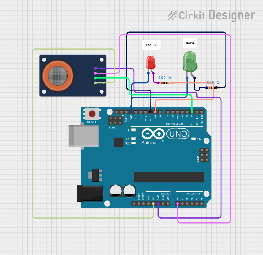
This circuit utilizes an Arduino UNO microcontroller to interface with an MQ-135 gas sensor and two LEDs (one red and one green). The MQ-135 sensor is used to detect air quality, while the LEDs provide visual feedback based on the sensor's output. The red LED indicates a dangerous air quality level, while the green LED indicates safe conditions. The circuit is designed to read analog and digital outputs from the sensor and display the results via the serial monitor.
Component List
Arduino UNO
- Description: A microcontroller board based on the ATmega328P.
- Purpose: Acts as the main control unit for the circuit, processing inputs from the MQ-135 sensor and controlling the LEDs.
LED Two Pin (Red)
- Description: A two-pin red LED.
- Purpose: Provides a visual indication of dangerous air quality levels.
LED Two Pin (Green)
- Description: A two-pin green LED.
- Purpose: Provides a visual indication of safe air quality levels.
Resistor (200 Ohm)
- Description: A resistor with a resistance of 200 Ohms.
- Purpose: Limits the current flowing through the LEDs to prevent damage.
MQ-135
- Description: An air quality sensor capable of detecting various gases.
- Purpose: Measures the air quality and provides analog and digital outputs to the Arduino.
Wiring Details
Arduino UNO
5V: Connected to the 5V pin of the MQ-135.
GND: Connected to the GND pin of the MQ-135 and the cathodes of both LEDs.
A0: Connected to the AOUT pin of the MQ-135.
D2: Connected to the DOUT pin of the MQ-135.
D9: Connected to the anode of the red LED through a resistor.
D10: Connected to the anode of the green LED through a resistor.
LED Two Pin (Red)
Cathode: Connected to GND.
Anode: Connected to D9 through a 200 Ohm resistor.
LED Two Pin (Green)
Cathode: Connected to GND.
Anode: Connected to D10 through a 200 Ohm resistor.
Resistor (200 Ohm)
pin1: Connected to the anode of the red LED.
pin2: Connected to D9 of the Arduino.
Resistor (200 Ohm)
pin1: Connected to the anode of the green LED.
pin2: Connected to D10 of the Arduino.
MQ-135
5V: Connected to the 5V pin of the Arduino.
GND: Connected to the GND pin of the Arduino.
AOUT: Connected to A0 of the Arduino.
DOUT: Connected to D2 of the Arduino.
Documented Code
const int PIN_AOUT = A0;
const int PIN_DOUT = 2;
const int LED_RED = 9;
const int LED_GREEN = 10;

void setup() {
  pinMode(PIN_DOUT, INPUT); // DOUT is active-low on LM393 modules
  pinMode(LED_RED, OUTPUT);
  pinMode(LED_GREEN, OUTPUT);
  digitalWrite(LED_RED, LOW);
  digitalWrite(LED_GREEN, LOW);
  Serial.begin(115200);
}

void loop() {
  int raw = analogRead(PIN_AOUT);
  float volts = raw * (5.0f / 1023.0f);

  int doLevel = digitalRead(PIN_DOUT);      // LOW = danger (above threshold), HIGH = safe
  bool danger = (doLevel == LOW);

  digitalWrite(LED_RED, danger ? HIGH : LOW);
  digitalWrite(LED_GREEN, danger ? LOW : HIGH);

  Serial.print("AOUT=");
  Serial.print(raw);
  Serial.print(" (");
  Serial.print(volts, 3);
  Serial.print(" V)  DOUT=");
  Serial.println(doLevel == LOW ? "LOW (DANGER)" : "HIGH (SAFE)");

  delay(100);
}
This documentation provides a comprehensive overview of the circuit, detailing each component, its purpose, wiring connections, and the code used to operate the system.