
ESP32-Based Smart Irrigation System with Soil Moisture Sensor and Battery-Powered Water Pump
View and Edit Project In Cirkit Designer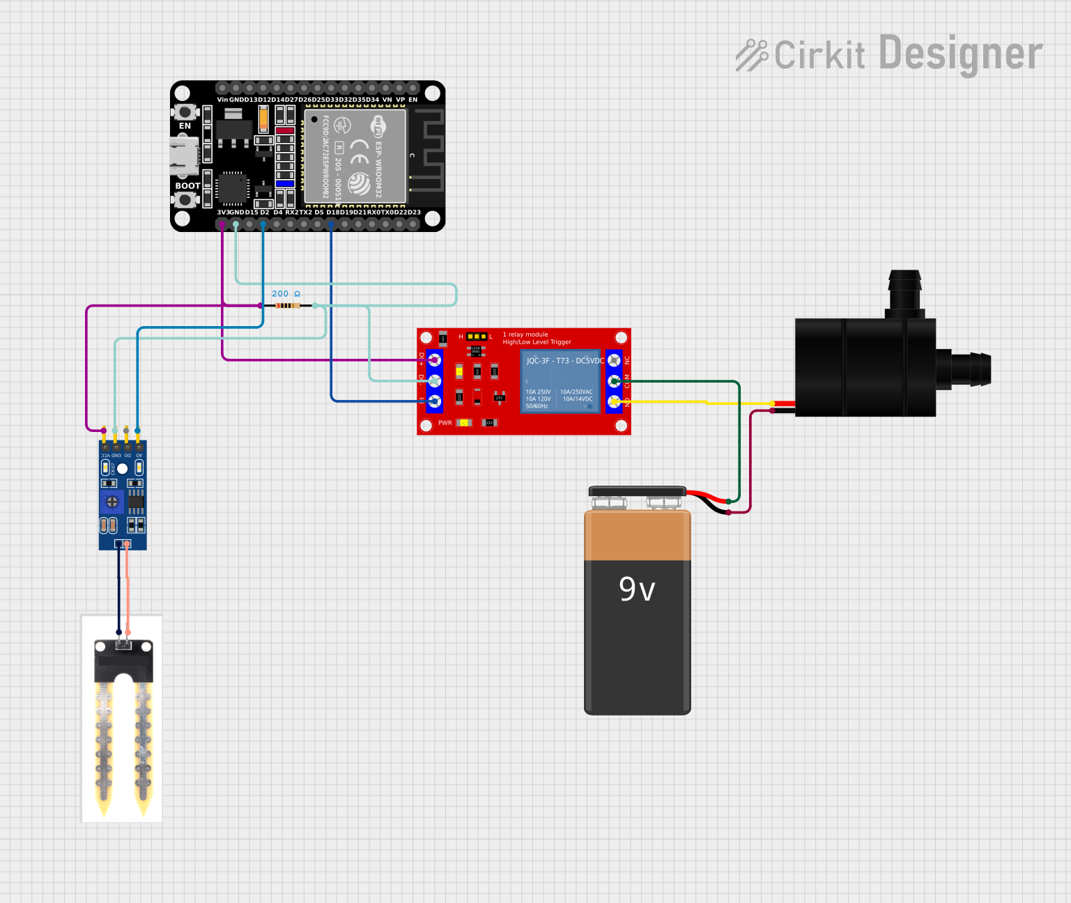
Circuit Documentation
Summary
This circuit is designed to control a water pump based on soil moisture levels using an ESP32 microcontroller. The system includes a soil moisture sensor, a relay module, and a water pump. The ESP32 reads the soil moisture levels and activates the relay to power the water pump when necessary.
Component List
ESP32 (30 pin)
- Description: A versatile microcontroller with Wi-Fi and Bluetooth capabilities.
- Pins: EN, VP, VN, D34, D35, D32, D33, D25, D26, D27, D14, D12, D13, GND, Vin, D23, D22, TX0, RX0, D21, D19, D18, D5, TX2, RX2, D4, D2, D15, 3V3
1 Channel 5V Relay Module
- Description: A relay module used to control high voltage devices with a low voltage signal.
- Pins: VCC+, VCC- (GND), IN, N.O., COM, N.C.
Water Pump
- Description: A pump used to move water.
- Pins: VCC, GND
9V Battery
- Description: A power source for the water pump.
- Pins: +, -
LM393
- Description: A comparator used to read the soil moisture sensor.
- Pins: A0, D0, GND, VCC
Soil Moisture Sensor
- Description: A sensor used to measure the moisture level in the soil.
- Pins: positive, negative
Resistor
- Description: A 200 Ohms resistor used in the circuit.
- Pins: pin1, pin2
- Properties: Resistance = 200 Ohms
Wiring Details
ESP32 (30 pin)
- D18 is connected to IN of the 1 Channel 5V Relay Module.
- D2 is connected to A0 of the LM393.
- GND is connected to pin2 of the Resistor, VCC- (GND) of the 1 Channel 5V Relay Module, and GND of the LM393.
- 3V3 is connected to pin1 of the Resistor, VCC+ of the 1 Channel 5V Relay Module, and VCC of the LM393.
1 Channel 5V Relay Module
- IN is connected to D18 of the ESP32.
- VCC- (GND) is connected to GND of the ESP32, pin2 of the Resistor, and GND of the LM393.
- VCC+ is connected to 3V3 of the ESP32, pin1 of the Resistor, and VCC of the LM393.
- N.O. is connected to VCC of the Water Pump.
- COM is connected to + of the 9V Battery.
Water Pump
- VCC is connected to N.O. of the 1 Channel 5V Relay Module.
- GND is connected to - of the 9V Battery.
9V Battery
- + is connected to COM of the 1 Channel 5V Relay Module.
- - is connected to GND of the Water Pump.
LM393
- A0 is connected to D2 of the ESP32.
- GND is connected to GND of the ESP32, pin2 of the Resistor, and VCC- (GND) of the 1 Channel 5V Relay Module.
- VCC is connected to 3V3 of the ESP32, pin1 of the Resistor, and VCC+ of the 1 Channel 5V Relay Module.
Soil Moisture Sensor
- negative is connected to GND of the LM393.
- positive is connected to VCC of the LM393.
Resistor
- pin1 is connected to 3V3 of the ESP32, VCC+ of the 1 Channel 5V Relay Module, and VCC of the LM393.
- pin2 is connected to GND of the ESP32, VCC- (GND) of the 1 Channel 5V Relay Module, and GND of the LM393.
Documented Code
sketch.ino
void setup() {
  // put your setup code here, to run once:
  Serial.begin(9600);
}

void loop() {
  // put your main code here, to run repeatedly:
  Serial.print("ceva");
}
documentation.txt