Cirkit Designer
Your all-in-one circuit design IDE
Home /
Project Documentation
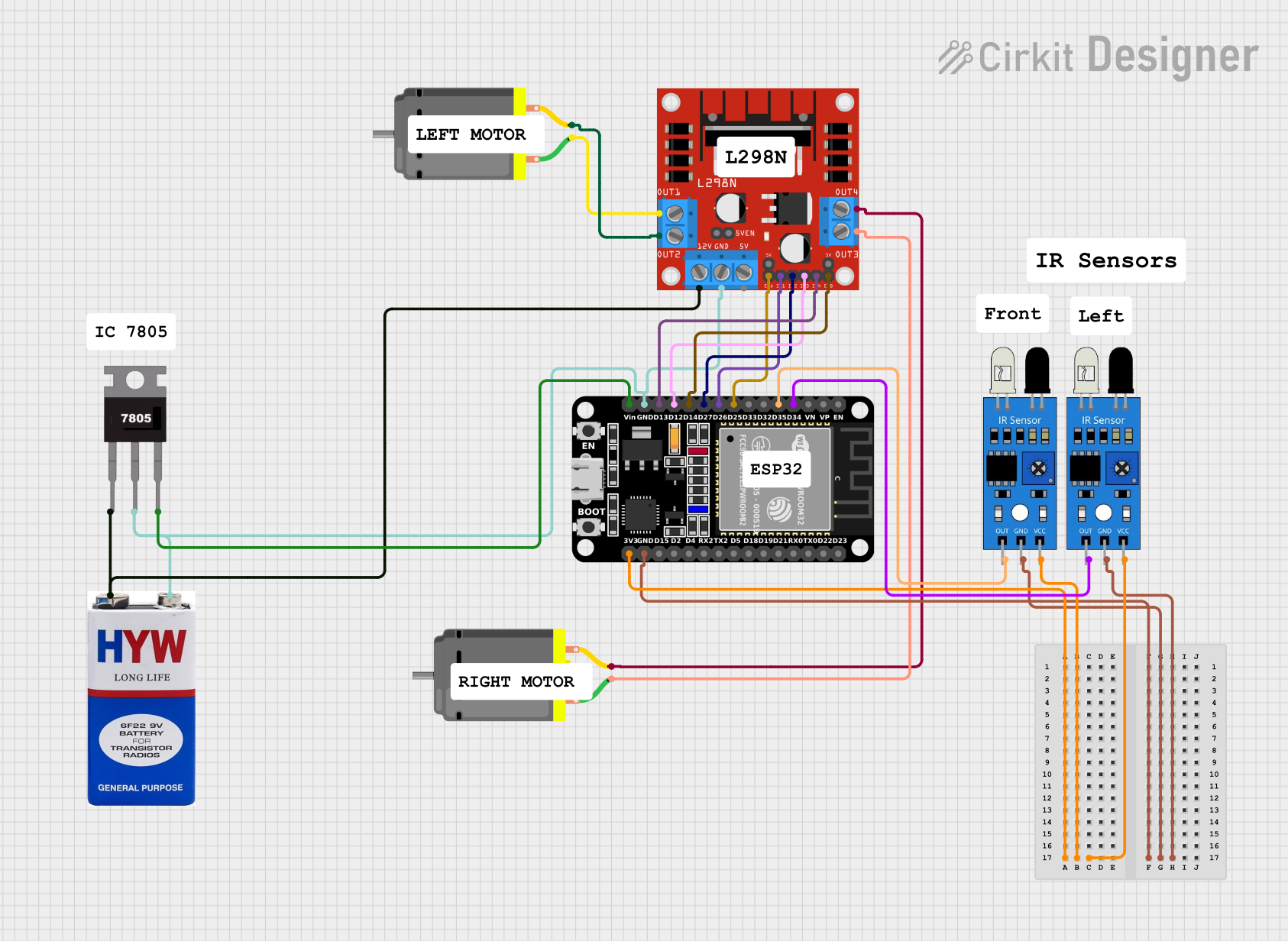
ESP32 and L298N-Based Obstacle Avoiding Robot with IR Sensors
Circuit Documentation
Summary
This circuit is designed to control two DC motors using an ESP32 microcontroller and an L298N motor driver. The circuit also includes two IR sensors for obstacle detection. The ESP32 reads the IR sensor inputs and controls the motors accordingly to navigate around obstacles. A 9V battery powers the entire circuit, with a 7805 voltage regulator providing a stable 5V supply to the components.
Component List
ESP32 (30 pin)
- Description: A powerful microcontroller with built-in Wi-Fi and Bluetooth capabilities.
- Pins: EN, VP, VN, D34, D35, D32, D33, D25, D26, D27, D14, D12, D13, GND, Vin, D23, D22, TX0, RX0, D21, D19, D18, D5, TX2, RX2, D4, D2, D15, 3V3
L298N DC Motor Driver
- Description: A dual H-bridge motor driver that allows control of two DC motors.
- Pins: OUT1, OUT2, 12V, GND, 5V, OUT3, OUT4, 5V-ENA-JMP-I, 5V-ENA-JMP-O, +5V-J1, +5V-J2, ENA, IN1, IN2, IN3, IN4, ENB
DC Motor (2 units)
- Description: Standard DC motors used for driving the robot.
- Pins: pin 1, pin 2
IR Sensor (2 units)
- Description: Infrared sensors used for obstacle detection.
- Pins: out, gnd, vcc
9V Battery
- Description: Provides power to the circuit.
- Pins: +, -
7805 Voltage Regulator
- Description: Regulates the 9V battery voltage down to 5V.
- Pins: Vin, Gnd, Vout
Wiring Details
ESP32 (30 pin)
- 3V3: Connected to
vccof both IR sensors. - GND: Connected to
gndof both IR sensors,GNDof L298N motor driver, andGndof 7805 voltage regulator. - D34: Connected to
outof the first IR sensor. - D35: Connected to
outof the second IR sensor. - D25: Connected to
ENAof L298N motor driver. - D26: Connected to
IN1of L298N motor driver. - D27: Connected to
IN2of L298N motor driver. - D14: Connected to
ENBof L298N motor driver. - D12: Connected to
IN3of L298N motor driver. - D13: Connected to
IN4of L298N motor driver. - Vin: Connected to
Voutof 7805 voltage regulator.
L298N DC Motor Driver
- OUT1: Connected to
pin 1of the first DC motor. - OUT2: Connected to
pin 2of the first DC motor. - OUT3: Connected to
pin 1of the second DC motor. - OUT4: Connected to
pin 2of the second DC motor. - 12V: Connected to
+of the 9V battery. - GND: Connected to
GNDof ESP32,Gndof 7805 voltage regulator, and-of the 9V battery. - ENA: Connected to
D25of ESP32. - IN1: Connected to
D26of ESP32. - IN2: Connected to
D27of ESP32. - ENB: Connected to
D14of ESP32. - IN3: Connected to
D12of ESP32. - IN4: Connected to
D13of ESP32.
DC Motor (First Unit)
- pin 1: Connected to
OUT1of L298N motor driver. - pin 2: Connected to
OUT2of L298N motor driver.
DC Motor (Second Unit)
- pin 1: Connected to
OUT3of L298N motor driver. - pin 2: Connected to
OUT4of L298N motor driver.
IR Sensor (First Unit)
- vcc: Connected to
3V3of ESP32. - gnd: Connected to
GNDof ESP32. - out: Connected to
D34of ESP32.
IR Sensor (Second Unit)
- vcc: Connected to
3V3of ESP32. - gnd: Connected to
GNDof ESP32. - out: Connected to
D35of ESP32.
9V Battery
- +: Connected to
Vinof 7805 voltage regulator and12Vof L298N motor driver. - -: Connected to
Gndof 7805 voltage regulator,GNDof L298N motor driver, andGNDof ESP32.
7805 Voltage Regulator
- Vin: Connected to
+of the 9V battery. - Gnd: Connected to
-of the 9V battery,GNDof L298N motor driver, andGNDof ESP32. - Vout: Connected to
Vinof ESP32.
Documented Code
ESP32 Code
void setup() {
  // put your setup code here, to run once:

}

void loop() {
// Define motor control pins
#define MOTOR1_IN1 14  // Motor 1 (left side)
#define MOTOR1_IN2 27
#define MOTOR2_IN3 26  // Motor 2 (right side)
#define MOTOR2_IN4 25

// Define IR sensor pins (front, left, right)
#define IR_SENSOR_FRONT 33
#define IR_SENSOR_LEFT 32
#define IR_SENSOR_RIGHT 35

// Function to move forward
void moveForward() {
  digitalWrite(MOTOR1_IN1, HIGH);
  digitalWrite(MOTOR1_IN2, LOW);
  digitalWrite(MOTOR2_IN3, HIGH);
  digitalWrite(MOTOR2_IN4, LOW);
}

// Function to move backward
void moveBackward() {
  digitalWrite(MOTOR1_IN1, LOW);
  digitalWrite(MOTOR1_IN2, HIGH);
  digitalWrite(MOTOR2_IN3, LOW);
  digitalWrite(MOTOR2_IN4, HIGH);
}

// Function to stop
void stopRobot() {
  digitalWrite(MOTOR1_IN1, LOW);
  digitalWrite(MOTOR1_IN2, LOW);
  digitalWrite(MOTOR2_IN3, LOW);
  digitalWrite(MOTOR2_IN4, LOW);
}

// Function to turn left
void turnLeft() {
  digitalWrite(MOTOR1_IN1, LOW);  // Stop left motors
  digitalWrite(MOTOR1_IN2, LOW);
  digitalWrite(MOTOR2_IN3, HIGH); // Run right motors
  digitalWrite(MOTOR2_IN4, LOW);
}

// Function to turn right
void turnRight() {
  digitalWrite(MOTOR1_IN1, HIGH); // Run left motors
  digitalWrite(MOTOR1_IN2, LOW);
  digitalWrite(MOTOR2_IN3, LOW);  // Stop right motors
  digitalWrite(MOTOR2_IN4, LOW);
}

// Setup function
void setup() {
  // Initialize motor control pins
  pinMode(MOTOR1_IN1, OUTPUT);
  pinMode(MOTOR1_IN2, OUTPUT);
  pinMode(MOTOR2_IN3, OUTPUT);
  pinMode(MOTOR2_IN4, OUTPUT);

  // Initialize IR sensor pins
  pinMode(IR_SENSOR_FRONT, INPUT);
  pinMode(IR_SENSOR_LEFT, INPUT);
  pinMode(IR_SENSOR_RIGHT, INPUT);

  // Initialize serial communication for debugging
  Serial.begin(115200);
}

// Main loop
void loop() {
  // Read IR sensors
  bool frontObstacle = digitalRead(IR_SENSOR_FRONT);
  bool leftObstacle = digitalRead(IR_SENSOR_LEFT);
  bool rightObstacle = digitalRead(IR_SENSOR_RIGHT);

  if (!frontObstacle) {
    // No obstacle in front, move forward
    moveForward();
  } else if (!rightObstacle) {
    // Obstacle in front, no obstacle on the right, turn right
    turnRight();
    delay(300);  // Small delay for turning
  } else if (!leftObstacle) {
    // Obstacle in front and right, no obstacle on the left, turn left
    turnLeft();
    delay(300);  // Small delay for turning
  } else {
    // Obstacles on all sides, move backward
    moveBackward();
    delay(300);  // Small delay for reversing
  }

  delay(100);  // Short delay for stability
}

}
Second Microcontroller Code