
Arduino and ESP32-Based Smart Fan Controller with LCD Display and Temperature/Humidity Sensors
View and Edit Project In Cirkit Designer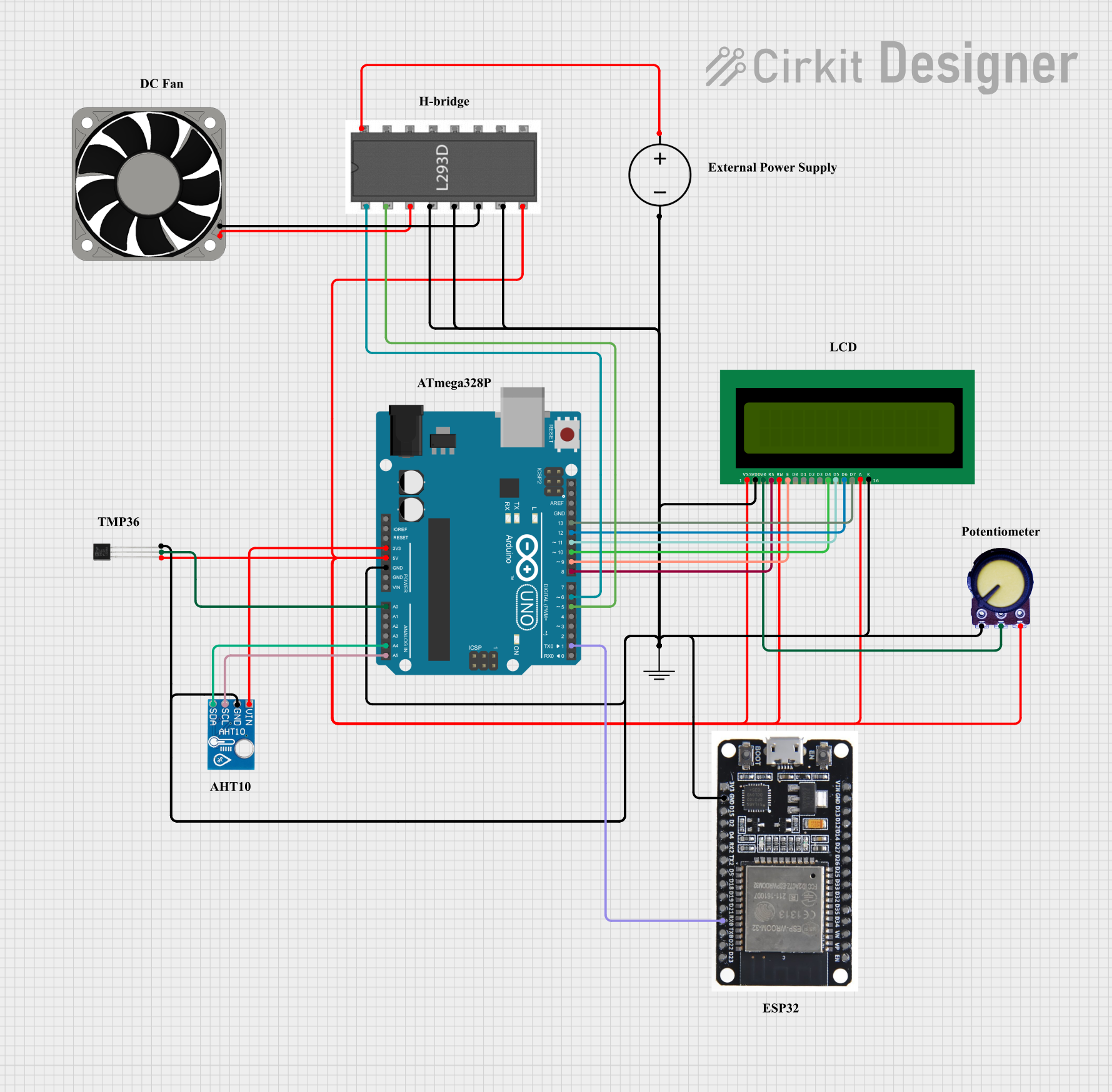
Circuit Documentation
Summary
This circuit involves an Arduino UNO microcontroller interfacing with various components including a 16x2 LCD display, a 12V fan, a potentiometer, an AHT10 sensor, a TMP36 temperature sensor, an ESP32 module, and an L293D motor driver. The circuit is powered by a DC power source and includes several ground connections.
Component List
16x2 LCD Display
- Description: A 16x2 character LCD display.
- Pins: VSS, VDD, V0, RS, RW, E, D1, D0, D2, D3, D4, D6, D5, D7, A, K
Arduino UNO
- Description: A microcontroller board based on the ATmega328P.
- Pins: UNUSED, IOREF, Reset, 3.3V, 5V, GND, Vin, A0, A1, A2, A3, A4, A5, SCL, SDA, AREF, D13, D12, D11, D10, D9, D8, D7, D6, D5, D4, D3, D2, D1, D0
12V Fan
- Description: A 12V DC fan.
- Pins: +12V, -12V
Potentiometer
- Description: A variable resistor.
- Pins: GND, Output, VCC
AHT10 Sensor
- Description: A temperature and humidity sensor.
- Pins: VIN, GND, SCL, SDA
TMP36 Sensor
- Description: A temperature sensor.
- Pins: VSS, PIN, GND
GND
- Description: Ground connection.
- Pins: GND
DC Power Source
- Description: A DC power source.
- Pins: Ground, Positive
ESP32
- Description: A microcontroller with Wi-Fi and Bluetooth capabilities.
- Pins: EN, VP, VN, D34, D35, D32, D33, D25, D26, D27, D14, D12, D13, GND, VIN, 3V3, D15, D2, D4, RX2, TX2, D5, D18, D19, D21, RX0, TX0, D22, D23, BOOT
L293D Motor Driver
- Description: A quadruple high-current half-H driver.
- Pins: Enable 1,2, Input 1, Output 1, GND, Output 2, Input 2, Vcc2, Vcc1, Input 4, Output 4, Output 3, Input 3, Enable 3,4
Wiring Details
16x2 LCD Display
- VSS connected to 5V of Arduino UNO
- VDD connected to GND
- V0 connected to Output of Potentiometer
- RS connected to D8 of Arduino UNO
- RW connected to 5V of Arduino UNO
- E connected to D9 of Arduino UNO
- D4 connected to D10 of Arduino UNO
- D5 connected to D11 of Arduino UNO
- D6 connected to D12 of Arduino UNO
- D7 connected to D13 of Arduino UNO
- A connected to 5V of Arduino UNO
- K connected to GND
Arduino UNO
- D6 connected to Enable 1,2 of L293D
- D5 connected to Input 1 of L293D
- 5V connected to VSS of TMP36, VCC of Potentiometer, VSS of 16x2 LCD, A of 16x2 LCD, RW of 16x2 LCD, Vcc2 of L293D
- 3.3V connected to VIN of AHT10
- A0 connected to PIN of TMP36
- A4 connected to SDA of AHT10
- A5 connected to SCL of AHT10
- D1 connected to RX0 of ESP32
12V Fan
- +12V connected to Output 1 of L293D
- -12V connected to Output 2 of L293D
Potentiometer
- GND connected to GND
- Output connected to V0 of 16x2 LCD
- VCC connected to 5V of Arduino UNO
AHT10 Sensor
- GND connected to GND
- VIN connected to 3.3V of Arduino UNO
- SCL connected to A5 of Arduino UNO
- SDA connected to A4 of Arduino UNO
TMP36 Sensor
- VSS connected to 5V of Arduino UNO
- PIN connected to A0 of Arduino UNO
- GND connected to GND
GND
- GND connected to GND of AHT10, TMP36, ESP32, Potentiometer, 16x2 LCD, DC Power Source, L293D, Arduino UNO
DC Power Source
- Ground connected to GND
- Positive connected to Vcc1 of L293D
ESP32
- GND connected to GND
- RX0 connected to D1 of Arduino UNO
L293D Motor Driver
- Enable 1,2 connected to D6 of Arduino UNO
- Input 1 connected to D5 of Arduino UNO
- Output 1 connected to +12V of 12V Fan
- GND connected to GND
- Output 2 connected to -12V of 12V Fan
- Input 2 connected to GND
- Vcc2 connected to 5V of Arduino UNO
- Vcc1 connected to Positive of DC Power Source
Code Documentation
Arduino UNO Code
void setup() {
  // put your setup code here, to run once:

}

void loop() {
  // put your main code here, to run repeatedly:

}
This code is a basic template for the Arduino UNO. The setup() function is where you initialize your components and settings, and the loop() function is where the main logic of your program runs repeatedly.