
ESP32-Controlled Environment Monitoring System with Wireless Communication and Relay Control
View and Edit Project In Cirkit Designer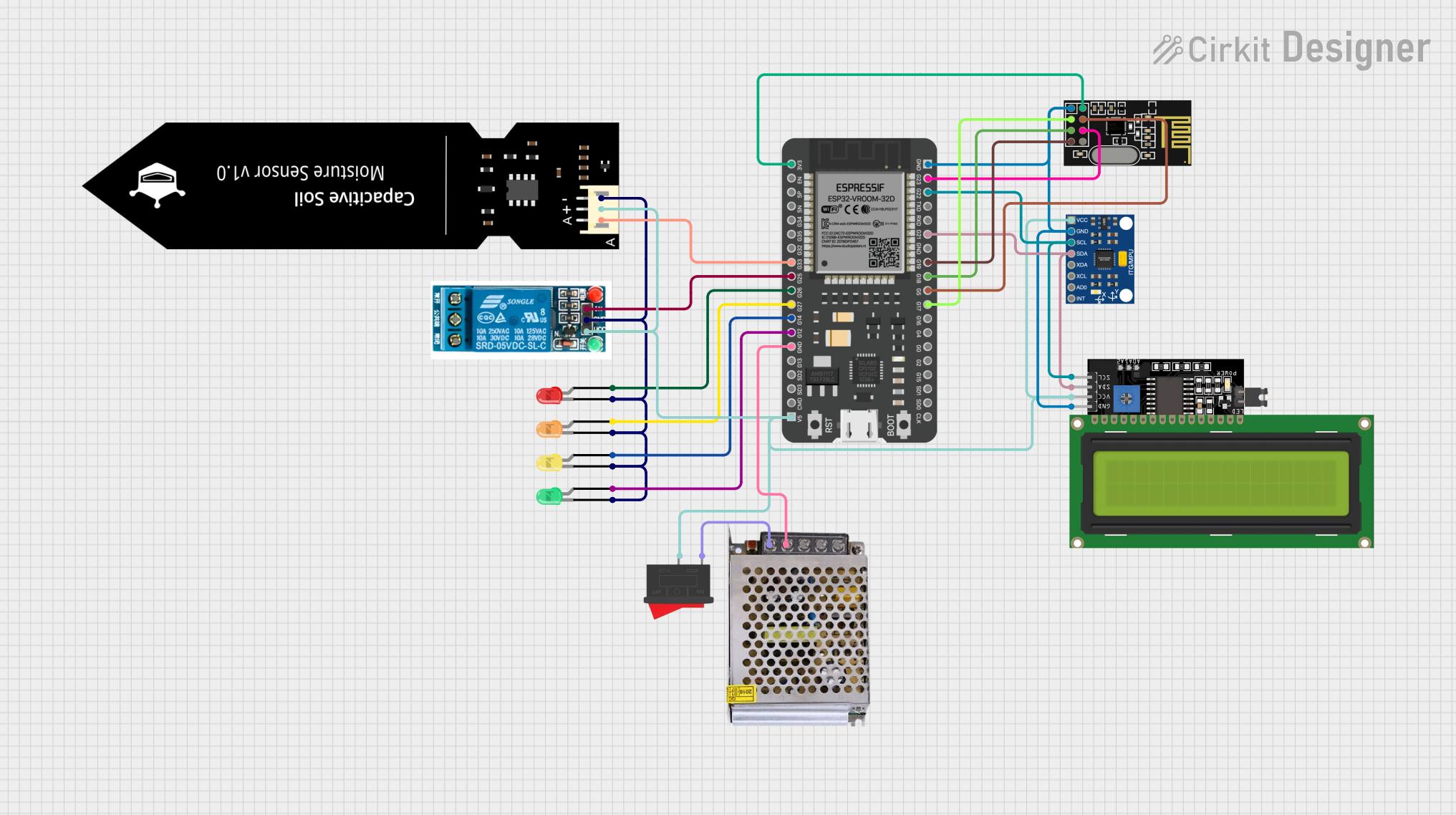
Circuit Documentation
Summary
This circuit integrates a variety of components including sensors, communication modules, a microcontroller, indicators, and a power supply. The primary controller is an ESP32 microcontroller, which interfaces with an InvenSense MPU6050 motion sensor, a DFRobot Capacitive Soil Moisture Sensor, and an NRF24L01 wireless communication module. The circuit also includes a 5V relay for controlling power to external devices and an LCD display for user interface. Power management is handled by a 5V power supply and a rocker switch. Indication is provided by a series of LEDs in different colors.
Component List
Microcontroller
- ESP32 - 38 pins: A powerful microcontroller with Wi-Fi and Bluetooth capabilities, featuring a wide range of GPIO pins for interfacing with various peripherals.
Sensors
- InvenSense MPU6050: A 6-axis motion tracking device that combines a 3-axis gyroscope and a 3-axis accelerometer.
- DFRobot Capacitive Soil Moisture Sensor (V1.0): A sensor for measuring the moisture content in soil.
Communication Module
- NRF24L01: A wireless transceiver module that operates in the 2.4GHz band, suitable for low-power, short-range communication.
Indicators
- LED: Two Pin (red)
- LED: Two Pin (green)
- LED: Two Pin (yellow)
- LED: Two Pin (orange): These LEDs are used as visual indicators for various statuses within the circuit.
Relay
- 5v relay: An electromechanical switch that allows the circuit to control higher power devices, operating at 5V.
Display
- LCD Display 16x4 I2C: A liquid crystal display with an I2C interface, used for displaying information to the user.
Power Supply
- POWER SUPPLY 5V 5AMP: Provides regulated 5V DC power to the circuit components.
Switch
- Rocker Switch: A mechanical switch used to control the power supply to the circuit.
Wiring Details
ESP32 - 38 pins
5Vconnected to the 5V power rail.GNDconnected to the ground rail.G22(SCL) connected to MPU6050 SCL and LCD Display SCL.G21(SDA) connected to MPU6050 SDA and LCD Display SDA.G33connected to DFRobot Capacitive Soil Moisture Sensor Analog Output.G23(MOSI) connected to NRF24L01 MOSI.G5(CSN) connected to NRF24L01 CSN.3V3connected to NRF24L01 VCC (3V).G17(CE) connected to NRF24L01 CE.G18(SCK) connected to NRF24L01 SCK.G19(MISO) connected to NRF24L01 MISO.G26connected to the anode of the red LED.G14connected to the anode of the yellow LED.G12connected to the anode of the green LED.G27connected to the anode of the orange LED.G25connected to the relay input.
InvenSense MPU6050
VCCconnected to the 5V power rail.GNDconnected to the ground rail.SCLconnected to ESP32 G22.SDAconnected to ESP32 G21.
DFRobot Capacitive Soil Moisture Sensor (V1.0)
Aconnected to ESP32 G33.VCCconnected to the 5V power rail.GNDconnected to the ground rail.
NRF24L01
MOSIconnected to ESP32 G23.CSNconnected to ESP32 G5.VCC (3V)connected to ESP32 3V3.GNDconnected to the ground rail.CEconnected to ESP32 G17.SCKconnected to ESP32 G18.MISOconnected to ESP32 G19.
LEDs (red, green, yellow, orange)
cathodeconnected to the ground rail.anodeconnected to respective ESP32 GPIO pins (G26, G14, G12, G27).
5v relay
VCCconnected to the 5V power rail.GNDconnected to the ground rail.Inconnected to ESP32 G25.
LCD Display 16x4 I2C
SCLconnected to ESP32 G22.SDAconnected to ESP32 G21.VCCconnected to the 5V power rail.GNDconnected to the ground rail.
POWER SUPPLY 5V 5AMP
GND (DC)connected to the ground rail.12V-24V Output (DC)connected to the Rocker Switch.
Rocker Switch
1connected to the 12V-24V Output (DC) from the power supply.2connected to the 5V power rail.
Documented Code
No code has been provided for the microcontrollers in the circuit. The documentation of the code would typically include descriptions of the functions, initialization routines, main loop, and any interrupt service routines. It would also detail how the code interacts with the hardware components listed above, such as reading sensor data, controlling the relay, updating the display, and managing wireless communication.